7 The DW1000 register set
The DW1000 is controlled by an associated host microcontroller system using the SPI interface to access a
series of registers within the device. The DW1000 register set includes configuration registers, status
registers, control registers, data buffer registers, and diagnostic registers. Section 2.2 – The SPI Interface
described the SPI interface and the low level transactions for reading and writing the parameters of the
DW1000. This section begins with 7.1– Register map overview and then 7.2– Detailed register description,
where each individual parameter is described in detail.
7.1 Register map overview
The register map overview is given in Table 15. This lists the registers in address order, by register file ID,
giving the register file length in octets, its type (RO = Read-Only, RW = Read & Write, SRW = Special Read
Write – see individual register descriptions for details about how the Read/Write access is special), and a
brief high level description of the register. Section 7.2 gives a detailed description of each register.
Note: When writing to any of the DW1000 registers care must be taken not to write beyond the published
length of the selected register and not to write to any of the reserved register locations. Doing so may cause
the device to malfunction.
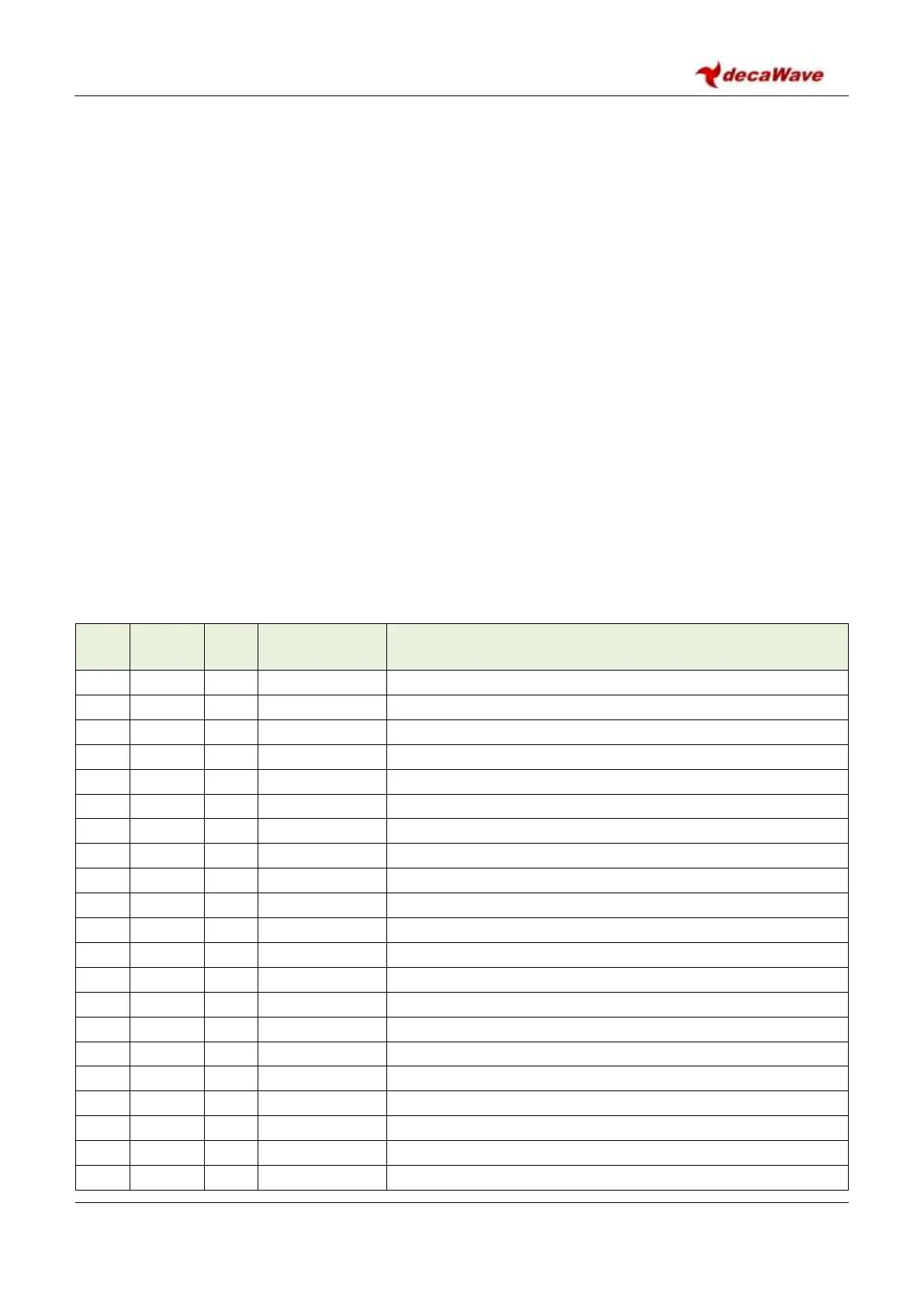
Table 15: Register map overview
Device Identifier – includes device type and revision info
Extended Unique Identifier
PAN Identifier and Short Address
System Configuration bitmap
System Time Counter (40-bit)
Delayed Send or Receive Time (40-bit)
Receive Frame Wait Timeout Period
System Event Mask Register
System Event Status Register
Rx Frame Quality information
Receiver Time Tracking Interval
Receiver Time Tracking Offset