The SR (“Special Register”) is a 32-bit segment of OTP that is directly readable via the register interface upon
power up. To programme the SR register follow the normal OTP programming method but set the OTP
address to 0x400. The value of the SR register can be directly read back at address Register file: 0x2D – OTP
Memory Interface.
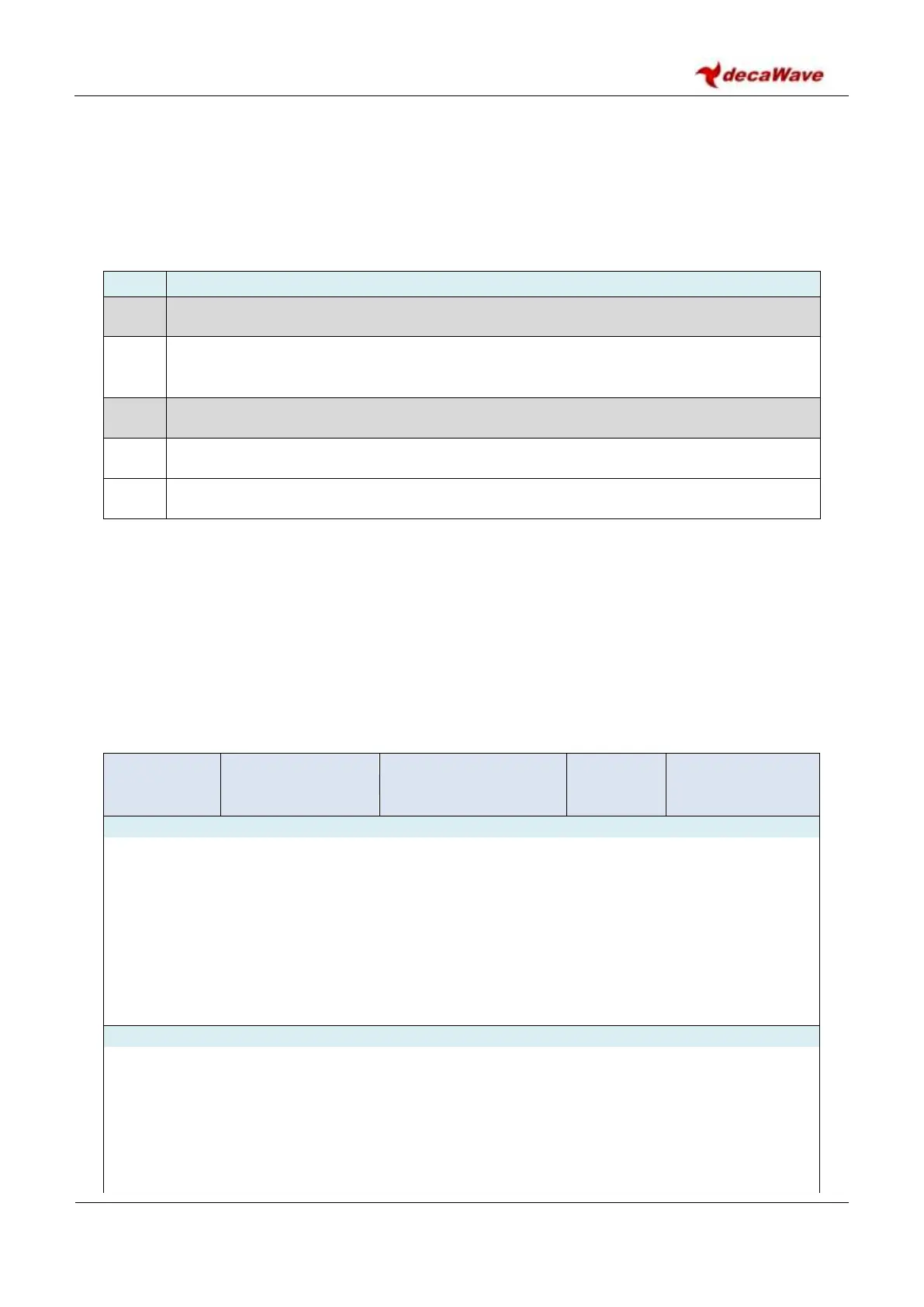
Table 11: OTP_SRDAT Register
Reserved. Defaults to all “0”. If programming the OTP_SRDATA register these bits must be set to “0”
SPI_SR_EN[1:0]. Set to “01” to enable bits [1:0] to be used instead of GPIO[6:5] boot
strapping. If set, this will disable the external selection of SPI mode via GPIO6 and 5.
Reserved. Defaults to “0”. If programming the OTP_SRDATA register these bits must be set to “0”
SPI_SR_PH. Set SPI Phase mode to this value if bits [4:3] are set to “01”
SPI_SR_POL. Set SPI Polarity mode to this value if bits [4:3] are set to “01”
6.3.2 Programming a value into OTP memory
The programming of the OTP requires a number of setup steps to be carried out in sequence. Optimal
programming requires that the VDDIO pin be driven to 3.8 V (or the VDDIOA pin if access to VDDIO is not
available). The table below outlines the programming steps to place the OTP into its programming state and
to programme a single location.
Table 12: Register accesses required to program the OTP
Configure OTP for Programming – Stage 1:
Configure OTP for Programming – Stage 2: