12 APPENDIX 3: Two-Way Ranging
12.1 Introduction
This appendix is for information only and describes various methods of implementing a two-way ranging
scheme between two nodes.
The chosen two-way ranging algorithm is implemented by host system software and is not a feature of the
DW1000. The DW1000 just provides the facilities for message time-stamping and precise control of message
transmission times that enable these algorithms. See section 4.1.6 – RX Message timestamp, 3.2 –
Transmission timestamp and 3.3 – Delayed Transmission for details of this.
In all of the schemes that follow one node acts as Initiator, initiating a range measurement, while the other
node acts as a Responder listening and responding to the initiator, and calculating the range.
12.2 Single-sided Two-way Ranging
Single-sided two-way ranging (SS-TWR) involves a simple measurement of the round trip delay of a single
message from one node to another and a response sent back to the original node.
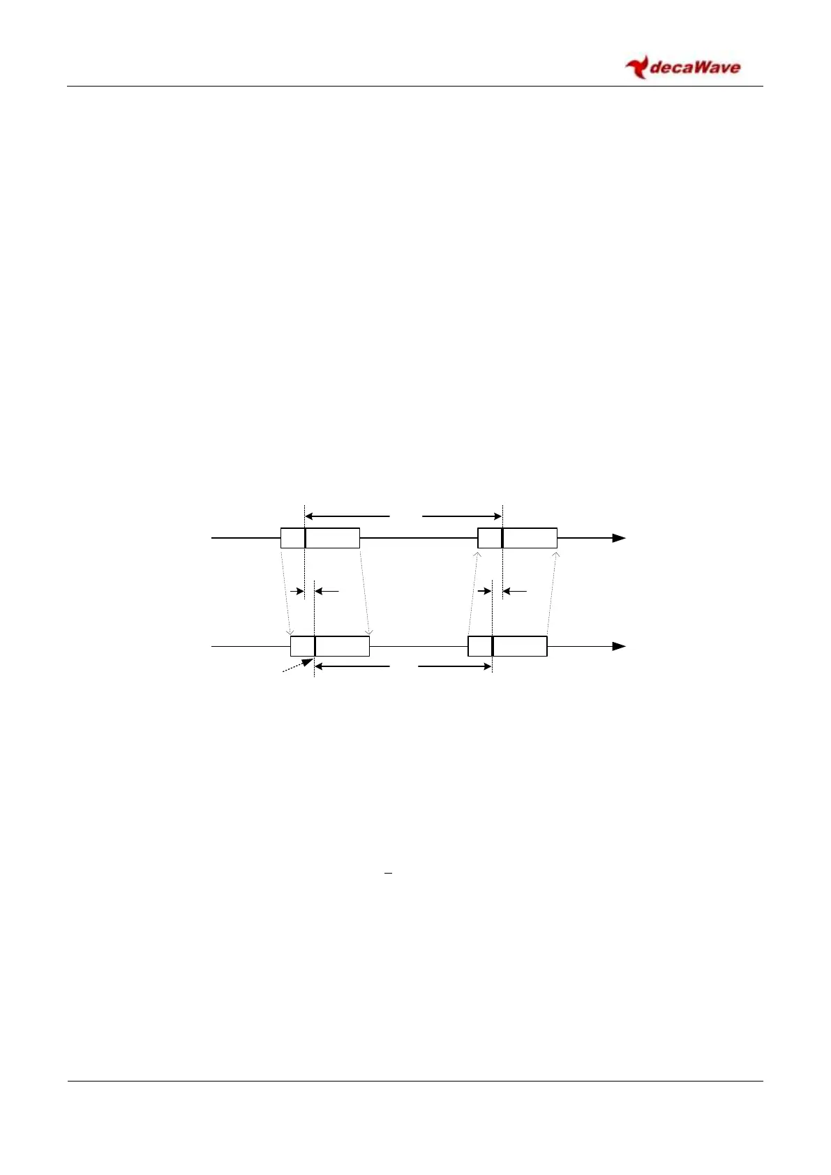
Figure 36: Single-sided Two-way ranging
The operation of SS-TWR is as shown in Figure 36, where device A initiates the exchange and device B
responds to complete the exchange and each device precisely timestamps the transmission and reception
times of the message frames, and so can calculate times T
round
and T
reply
by simple subtraction. And the
resultant time-of-flight, T
prop
may be estimated by the equation:
The times T
round
and T
reply
are measured independently by device A and B using their respective local clocks,
which both have some clock offset error e
A
and e
B
from their nominal frequency, and so the resulting time-
of-flight estimate has a considerable error that increases as T
reply
increases. Some typical values for this are
presented in Table 65. Depending on the size of ranging error that is acceptable to the application, SS-TWR
may be an appropriate choice for range measurement especially if the reply time T
reply
is minimized and the
clock error is low. It should be noted that the reply time T
reply
is not just the RX-to-TX turnaround time but
also includes the message length.
Device A
Device B
TX
T
prop
T
prop
RX
RX TX
T
reply
T
round
time
RMARKER


 To Next Page