Chapter 8 Logic Instructions
Output Update Timing
Timing for changing to TRUE
Timing for changing to FALSE
Done
When the writing of the
parameter content is completed
When Execute changes from
TRUE to FALSE after the
instruction execution is completed
Busy When Execute changes to TRUE
When Error changes to TRUE
When Done changes from FALSE
Active
When the slave starts being
controlled by the instruction
When Error changes to TRUE
When Done changes from FALSE
Error
When an error occurs in the
instruction execution or the input
parameters for the instruction are
illegal
When Execute changes from
TRUE to FALSE
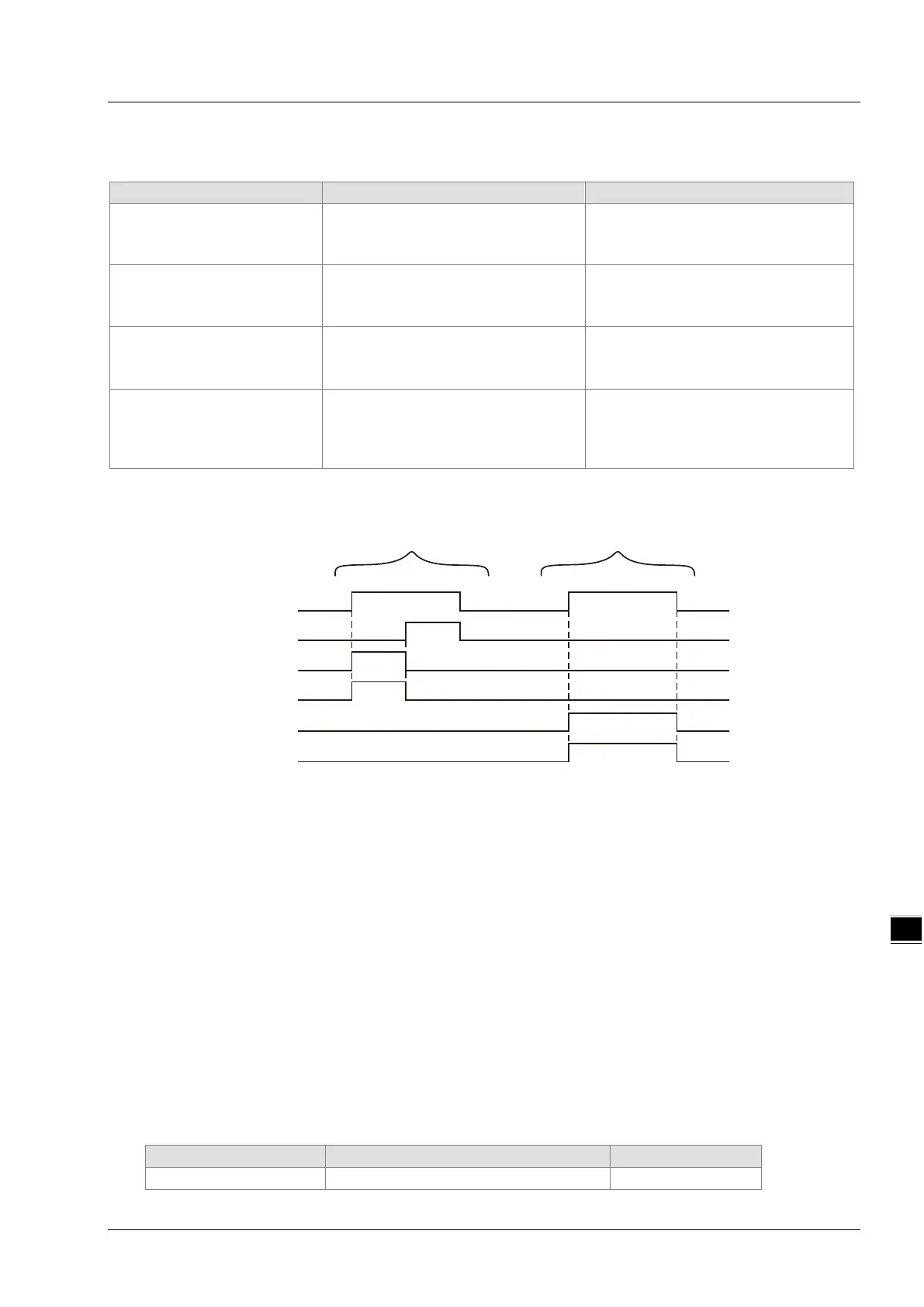
Timing Chart
Case 1: Busy and Active change to TRUE when Execute changes from FALSE to TRUE and one
period later, Done changes to TRUE. When Done changes to TRUE, Busy and Active change
to FALSE. When Execute changes from TRUE to FALSE, Done changes from TRUE to
FALSE.
Case 2: Before DMC_WriteParameter_CANopen is executed, the input parameter value such as axis
No: 0 is illegal. After Execute changes from FALSE to TRUE, Error changes from FALSE to
TRUE and ErrorID shows corresponding error codes. As Execute changes from TRUE to
FALSE, Error changes from TRUE to FALSE and the content of ErrorID is cleared to 0.
Function
DMC_WriteParameter_CANopen is used to set the parameter value of a slave. Users can specify the index
and subindex of the parameter which is to be set.
Programming Example
Below is an example of one DMC_WriteParameter_CANopen instruction execution.
The variable table and program
DMC_ReadParameter_CANopen
Execute
Done
Busy
Active
Error
ErrorID
Case1
Case2
8-183