DVP15MC11T Operation Manual
Figure 6.2.2.4
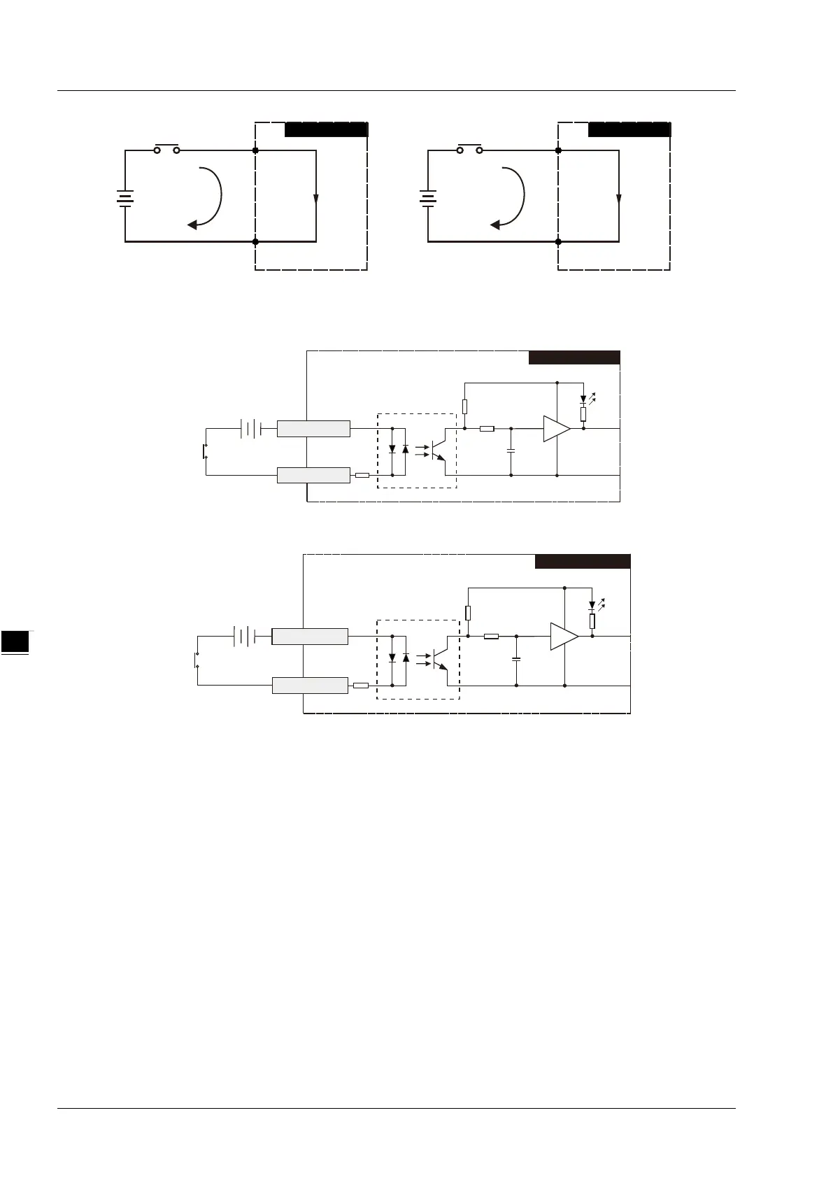
See the wiring circuit below
Figure 6.2.2.5
Figure 6.2.2.6
6.2.3 Output Point Wiring
All transistor outputs in DVP15MC11T contain diodes for suppression which are sufficient for use in the
inductive load of smaller power and infrequent On/Off. However, in the event of larger power and frequent
On/Off, the following suppression circuit is necessary for reducing interferences and preventing the transistor
output circuit from being damaged due to overvoltage or overheat.
S0
00
DVP15MC11T
Sourcing
24VDC
S1
10
DVP15MC11T
Sourcing
24VDC
DVP15MC11T
Switch
24VDC
S0 Common po rt( )
00 Input( )
DVP15MC11T
Switch
24VDC
S1 Common port( )
10 Input( )
6-6