Chapter 6 Wiring, Communication Setting and Network Construction
6
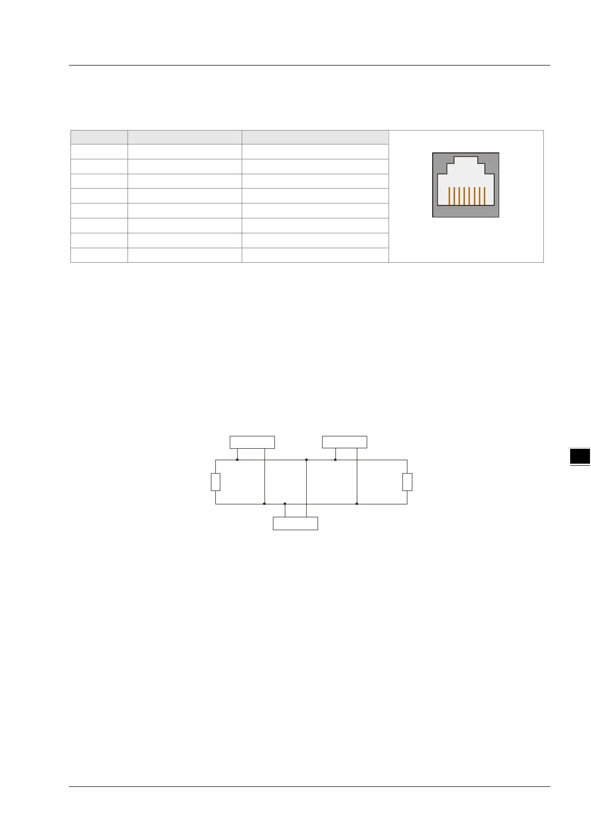
6.9.2 Pins of CANopen Communication Port
DVP15MC11T’s CANopen communication port is used in the standard CANopen communication and its pin
descriptions are listed in the following table.
6.9.3 PDO Mapping at CANopen Communication Port
The input mapping area is %MW5000~%MW5499 and output mapping area is %MW5500~%MW5999 when
DVP15MC11T works as CANopen master.
The input mapping area is %MW5000~%MW5031 and output mapping area is %MW5500~%MW5531 when
DVP15MC11T works as CANopen slave.
6.9.4 Network Connection at CANopen Communication Port
CANopen Bus Terminals and Network Topology
Both of the two ends of a CANopen network need be connected with the terminal resistors of 120Ω to
enhance the stability of CANopen communication. See the illustration of a basic CANopen network topology
below.
120 Ω
120Ω
CAN 1node CAN 2node
CAN 3node
CAN_H
CAN_L
6-21