Chapter 6 Wiring, Communication Setting and Network Construction
6
6.6 Incremental Encoders
6.6.1 Function of Incremental Encoder
DVP15MC11T’s incremental encoder port is a 15-pin D-SUB interface which can connect two independent
incremental encoders. Both of the two encoder ports support differential signal input with maximum work
frequency of 1MHz (250Kx 4 = 1MHz) per one. Additionally, the port integrates two 5V (400mA) power
outputs to supply power to the two encoders. Users can create an incremental encoder axis for either of the
two encoders to control the motion of slave axes according to the number of pulses received at the encoder
port.
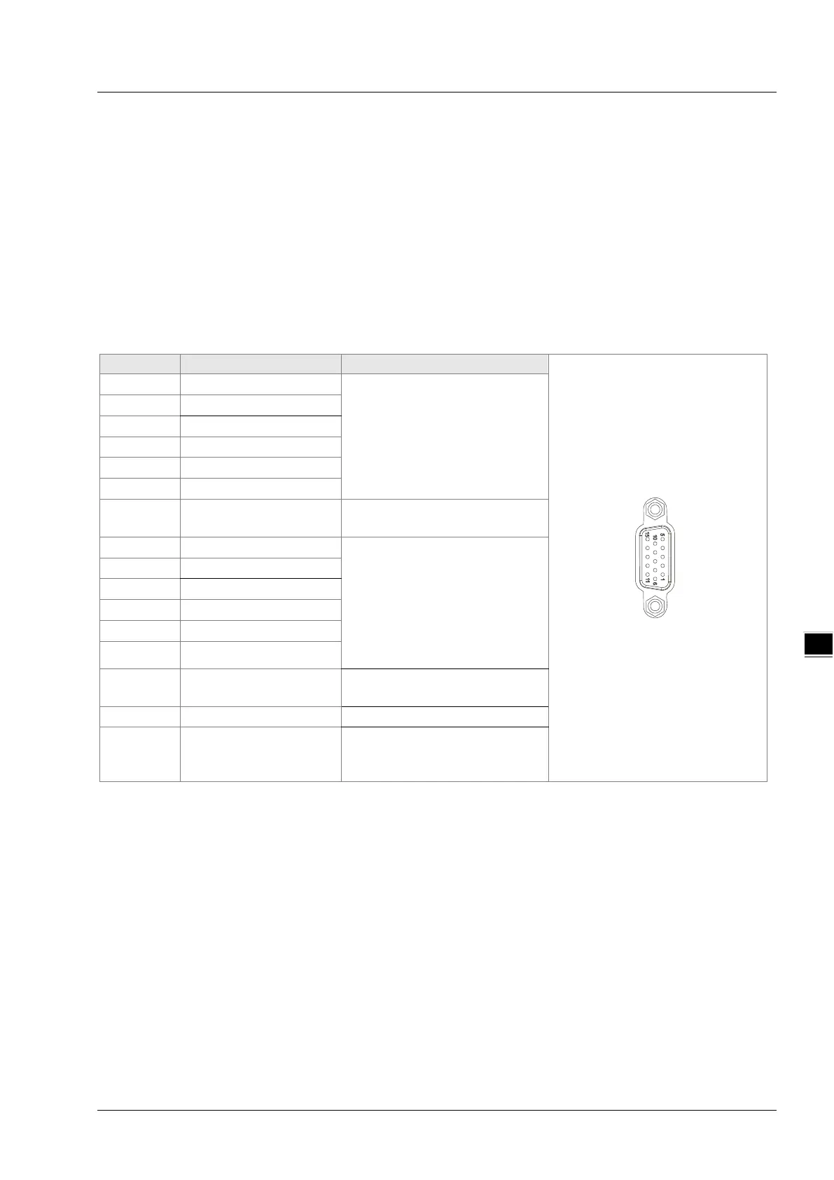
6.6.2 Definition of Incremental Encoder Port Pins
DVP15MC11T’s incremental encoder port is a 15-pin interface. See the table below for definitions of
respective encoder communication port pins.
Encoder
Differential signals of t
incremental encoder
4 Z1+
5 Z1-
15 +5V
Power supply for the first
Differential signals of the
second incremental encoder
14 Z2-
7 +5V
Power supply for the second
encoder
0V shared by the two encoders
metal
Shielding layer
6-15