Chapter 4 System Architecture
4.3.2 Allocation of Left-side Network Module Addresses
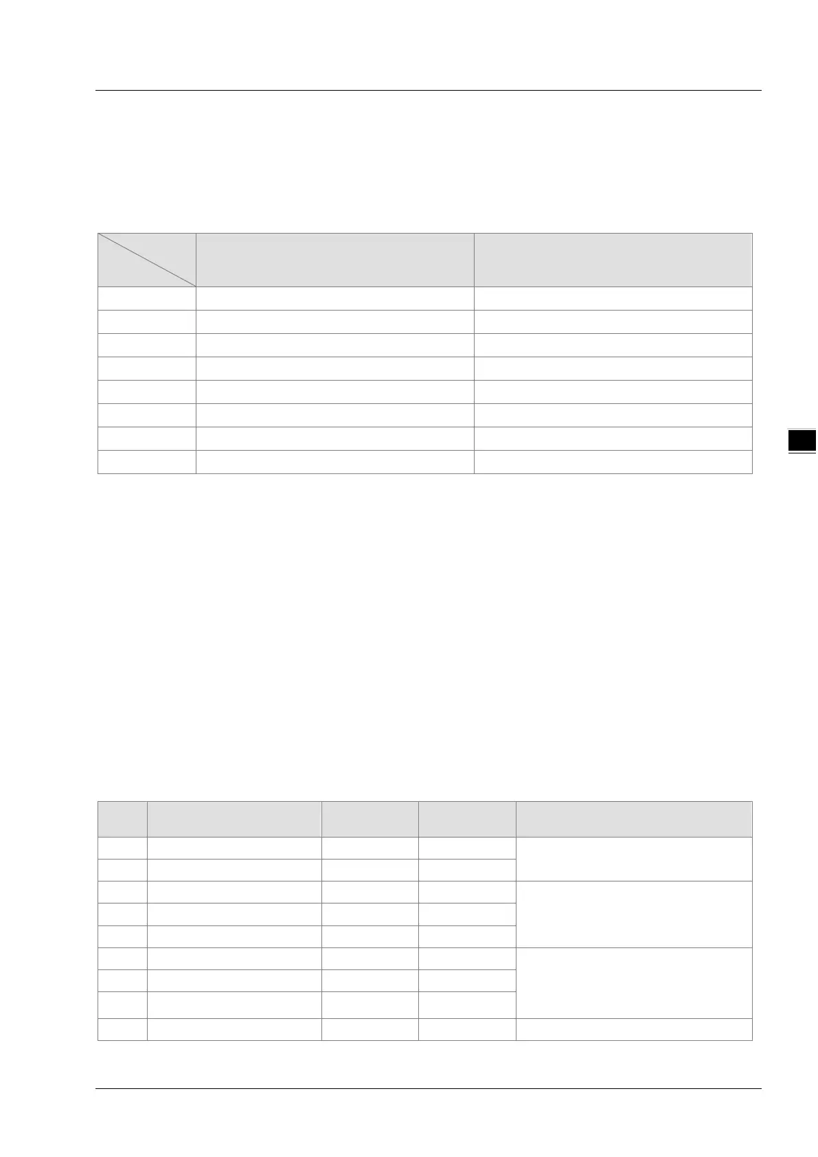
About Input and Output Mapping Areas of Left-side Network Modules
The input and output mapping areas of different positions of the left side of PLC CPU are listed as follows
when the network modules connected to the left side of DVP15MC11T serve as a slave. The position 1 is for
the first module connected to the left side of PLC CPU; the position 2 is for the second one connected to the
left side of PLC CPU and so on.
area
Output mapping area Input mapping area
1
%MW6250~%MW6377 %MW6000~%MW6127
2
%MW6750~%MW6877 %MW6500~%MW6627
3
%MW7250~%MW7377 %MW7000~%MW7127
4
%MW7750~%MW7877 %MW7500~%MW7627
5
%MW8250~%MW8377 %MW8000~%MW8127
6
%MW8750~%MW8877 %MW8500~%MW8627
7
%MW9250~%MW9377 %MW9000~%MW9127
8
%MW9750~%MW9877 %MW9500~%MW9627
Refer to the operation manuals of modules for details on allocation of left-side extension module mapping
areas. Pay attention to how the mapping address expression format is changed in the operation manual.
For example, the output mapping area for DVPPF02-SL is D6250~D6349. But the area address is expressed
as %MW6250~%MW6349 when the module is connected to the left of DVP15MC11T.
4.3.3 Method of Reading/Writing of Left-side Modules
The controller can read and write the data in CR registers of the left-side extension modules via FROM/TO
instruction. For instance, the modules such as DVP04AD-SL and DVP04DA-SL may use FROM/TO to read
and write data in CR.
4.4 Right-side Extension
4.4.1 Connectable Right-side Extension Modules
Slim-series extension modules including digital modules, analog modules and temperature modules can be
connected to the right side of DVP15MC11T. Digital modules can connect maximum 240 input points and 240
output points. Maximum 8 analog modules can be connected. The connectable right-side extension modules
are listed in the following table.
No. Module name
Extension type
1 DVP08SM11N 8 bits -
Input point extension
2 DVP16SM11N 16 bits -
3 DVP06SN11R - 6 bits
Output point extension
4 DVP08SN11R/T - 8 bits
5 DVP16SN11T - 16 bits
6
DVP08SP11R/T
4 bits
4 bits
Input extension and output
extension
8
DVP16SP11TS(PNP)
8 bits 8 bits
9 DVP32SM11N 32 bits - Pin-connector input
4-3