Chapter 6 Wiring, Communication Setting and Network Construction
6
6.7 Ethernet Communication Port
6.7.1 Function that Ethernet Communication Port Supports
There are two independent Ethernet communication ports in DVP15MC11T, which both support Modbus TCP
protocol. Of the two Ethernet ports, LAN1 port can only work as a slave and LAN2 port can work as a master
or a slave in the Ethernet network. Either of them can accept a maximum of 4 master access at a time and
their IP addresses need be set separately. HMI, PLC or other Modbus TCP master device can read and write
data in the devices inside DVP15MC11T via the two Ethernet ports. For details on Modbus TCP
communication, refer to appendix A.
Both of the two Ethernet ports can be used to download configuration files, execution files and CAM files.
They also support automatic jumper function and users do not need to additionally select wire jumper when
the Ethernet port is connected to the computer or switchboard. Besides, they can automatically detect the
transmission speed of 10Mbps and 100 Mbps as well.
The Ethernet communication port supports Ethernet/IP protocol, Ethernet/IP slaves only as well as maximum
200 bytes of input and maximum 200 bytes of output
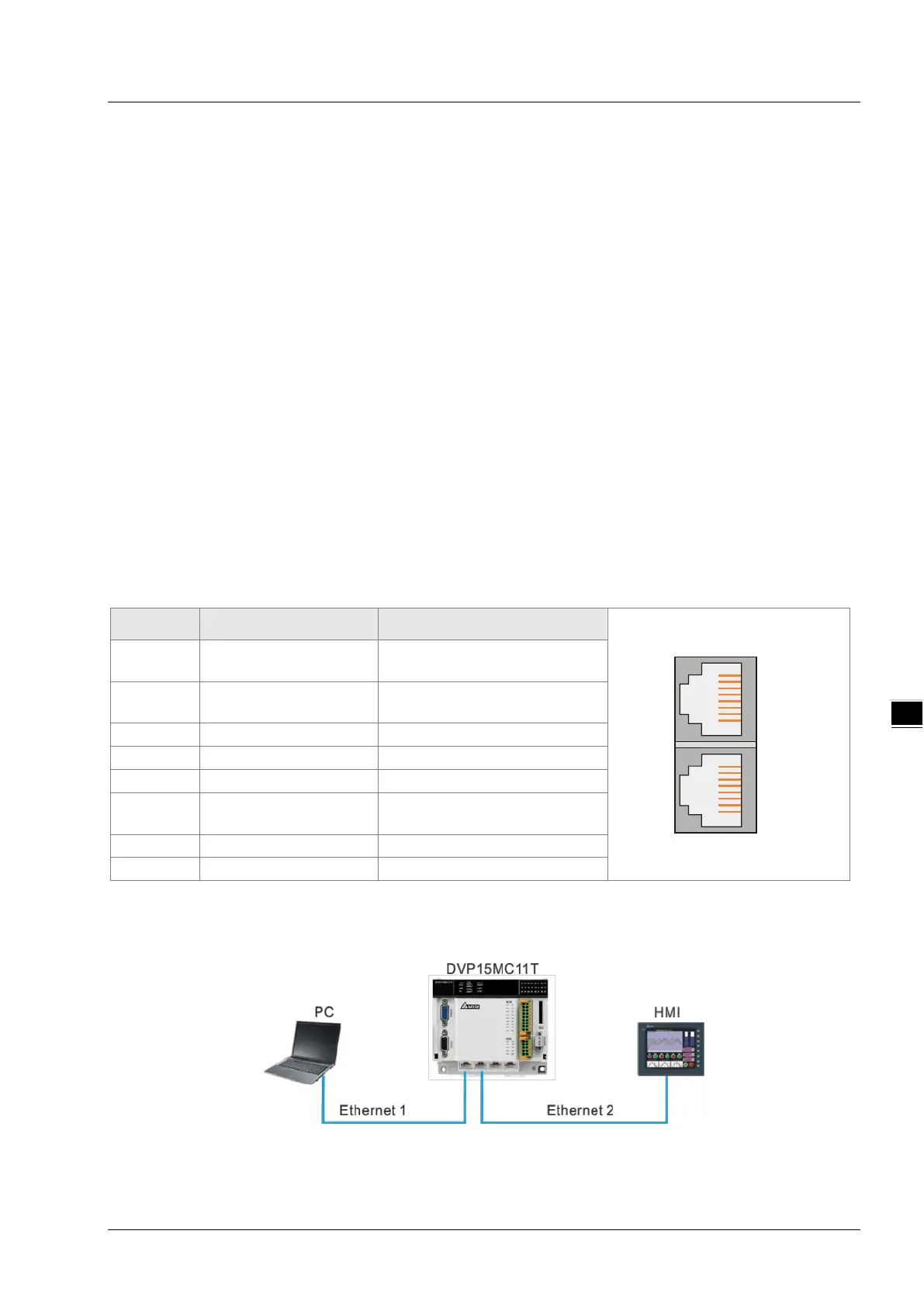
6.7.2 Pins of Ethernet Communication Port
DVP15MC11T has two independant Ethernet ports supporting Modbus TCP protocol with the pins shown in
the following table. The IP addresses of the two Ethernet ports need be set respectively. The default IP
address for LAN1 is 192.168.0.1 and the default IP address for LAN2 is 192.168.1.1.
Pin No. Signal Definition
1 Tx+
Positive pole for transmiting
data
2 Tx-
Negative pole for transmitting
data
Positive pole for receiving data
6 Rx-
Negative pole for receiving
7 Reserved Reserved
8 Reserved Reserved
6.7.3 Network Connection of Ethernet Communication Port
LAN 2LAN 1
1234567812345678
6-17