Chapter 7 Parameters ASDA-B2
7-24 Revision May, 2018
Pulse specification
Max. input
frequency
Min. time width
T1 T2 T3 T4 T5 T6
High-speed
pulse
Differential
Signal
4 Mpps 62.5ns 125ns 250ns 200ns 125ns 125ns
Low-speed
pulse
Differential
Signal
500 Kpps 0.5μs 1μs 2μs 2μs 1μs 1μs
Open
collector
200 Kpps 1.25μs 2.5μs 5μs 5μs 2.5μs 2.5μs
Pulse specification
Max. input
frequency
Voltage
specification
Forward
Current
High-speed pulse Differential Signal 4 Mpps 5V < 25 mA
Low-speed pulse
Differential Signal 500 Kpps 2.8V ~ 3.7V < 25 mA
Open collector 200 Kpps 24V (Max.) < 25 mA
Source of external
0: Low-speed optical coupler (CN1 Pin: PULSE, SIGN)
1: High-speed differential (CN1 Pin: HPULSE, HSIGN)
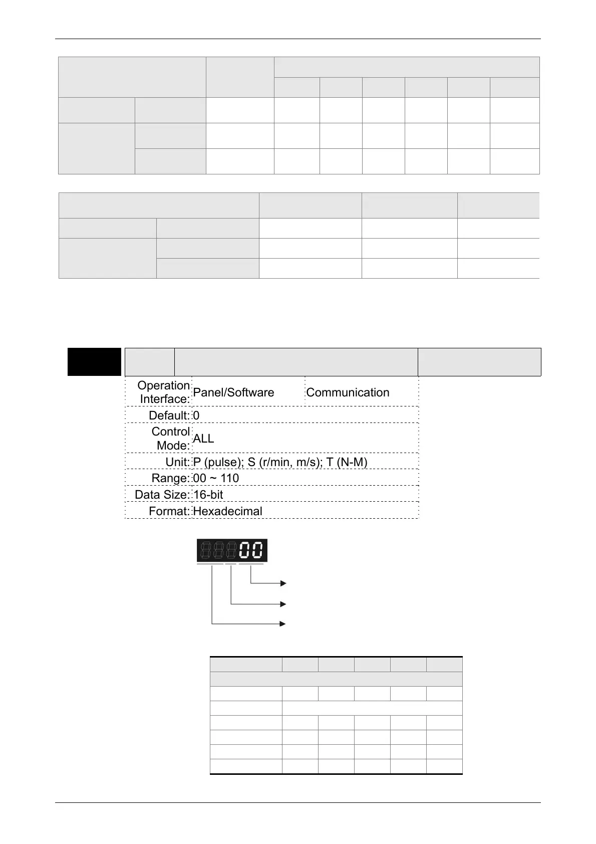
P1-01●
CTL Control Mode and Output Direction
Address: 0102H
0103H
Operation
Interface:
Panel/Software Communication
Related Section:
6.1, Table 7.1
Default: 0
Control
Mode:
ALL
Unit: P (pulse); S (r/min, m/s); T (N-M)
Range: 00 ~ 110
Data Size: 16-bit
Format: Hexadecimal
Settings:
Control mode setting
Mode PT S T Sz Tz
Single Mode
00 ▲
01 Reserved
02 ▲
03 ▲
04 ▲
05 ▲
Control mode setting
Torque output direction setting
Not in use
 Loading...


