ASDA-B2 Chapter 7 Parameters
Revision May, 2018 7-23
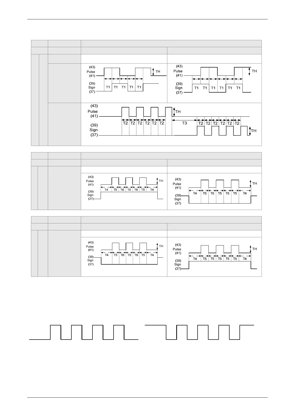
Logic Type
High-speed and Low-speed Pulse Input
Logic Pulse Type Forward Rotation Reverse Rotation
0
Positive Logic
Pulse Phase Lead Pulse Phase Lag
AB Phase
Pulse
Clockwise
and
Counter-
clockwise
Pulse
High-speed Pulse Input
Logic Pulse Type Forward Rotation Reverse Rotation
0
Positive Logic
Pulse +
Symbol
Sign = high Sign = low
Low-speed Pulse Input
Logic Pulse Type Forward Rotation Reverse Rotation
0
Positive Logic
Pulse +
Symbol
Sign = low Sign = high
Digital circuits use 0 and 1 to represent the high and low voltage levels. In positive logic,
1 represents high voltage and 0 represents low voltage; in negative logic, 1 represents low
voltage and 0 represents high voltage.
For example:
Positive Logic
Negative Logic
 Loading...


