Chapter 8 Communications ASDA-B2
8-8 Revision May, 2018
Communication Data Structure:
The data frame of two different communication modes is defined as follows:
ASCII Mode:
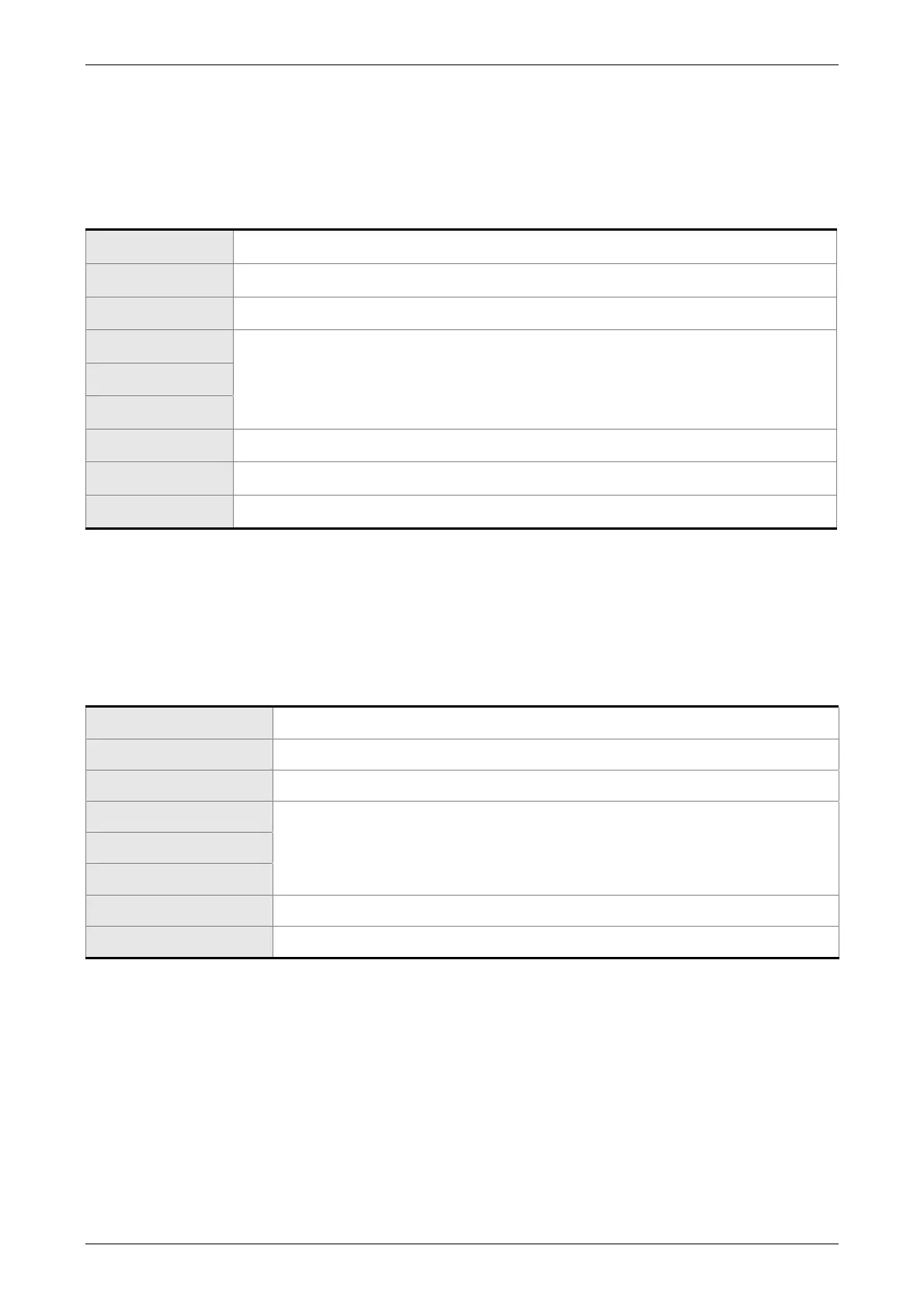
Start Start character’: ’ (3AH)
Slave address Communication address: 1-byte consists of 2 ASCII codes
Function Function code: 1-byte consists of 2 ASCII codes
DATA(n-1)
Data content: n word = n x 2-byte consists of n x 4 ASCII codes, n10
…….
DATA(0)
LRC Error checking: 1-byte consists of 2 ASCII codes
End 1 End code 1: (0DH)(CR)
End 0 End code 0: (0AH)(LF)
The start character of communication in ASCII mode is colon ‘:’ (ASCII is 3AH), ADR is
the ASCII code of two characters. The end code is CR (Carriage Return) and LF (Line
Feed). And the communication address, function code, data content, error checking LRC
(Longitudinal Redundancy Check), etc. are between the start character and end code.
RTU Mode:
Start A silent interval of more than 10 ms
Slave address Communication address: 1-byte
Function Function code: 1-byte
DATA(n-1)
Data content: n word = n x 2-byte, n 10
…….
DATA(0)
CRC Error checking: 1-byte
End 1 A silent interval of more than 10ms
The start of communication in RTU (Remote Terminal Unit) mode is a silent interval. The
end of it is another silent interval. The communication address, function code, data content,
error checking CRC (Cyclical Redundancy Check), etc. are between the start and the end.

 Loading...


