ASDA-B2 Chapter 3 Wiring
Revision May, 2018 3-31
The high-speed pulse input interface of the servo drive is not the
isolated interface. In order to reduce the interference of the noise, it is
suggested that the terminal ground of the controller and the servo drive
should be connected to each other.
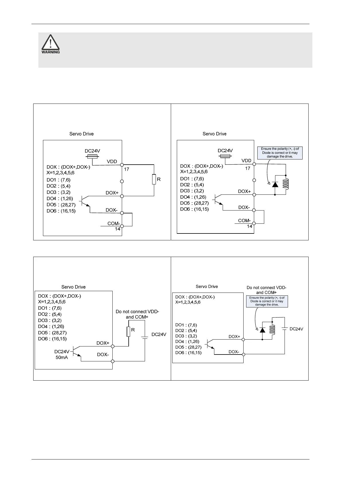
When the drive connects to inductive load, the diode has to be installed. (The permissible
current is under 40 mA; the surge current is under 100 mA; the maximum voltage is 30V.)
C5: Wiring of DO signal. The servo drive applies
to the internal power and the resistor is
general load.
C6: Wiring of DO signal. The servo drive applies
to the internal power and the resistor is
inductive load.
C7: Wiring of DO signal. The servo drive applies
to the external power and the resistor is
general load.
C8: Wiring of DO signal. The servo drive applies
to the external power and the resistor is
inductive load.
 Loading...


