EasyManuals Logo

Delta ASDA-B2 Series User Manual

Delta ASDA-B2 Series
345 pages
To Next Page IconTo Next Page
To Previous Page IconTo Previous Page
Page #71 background imageLoading...
Page #71 background image
Chapter 3 Wiring ASDA-B2
3-32 Revision May, 2018
The DI wiring inputs signal via the relay or open-collector transistor.
Conditions of DI On / Off:
ON: 15V - 24V; the input current is higher than 3 mA.
OFF: below 5V; the input current must not be higher than 0.5 mA.
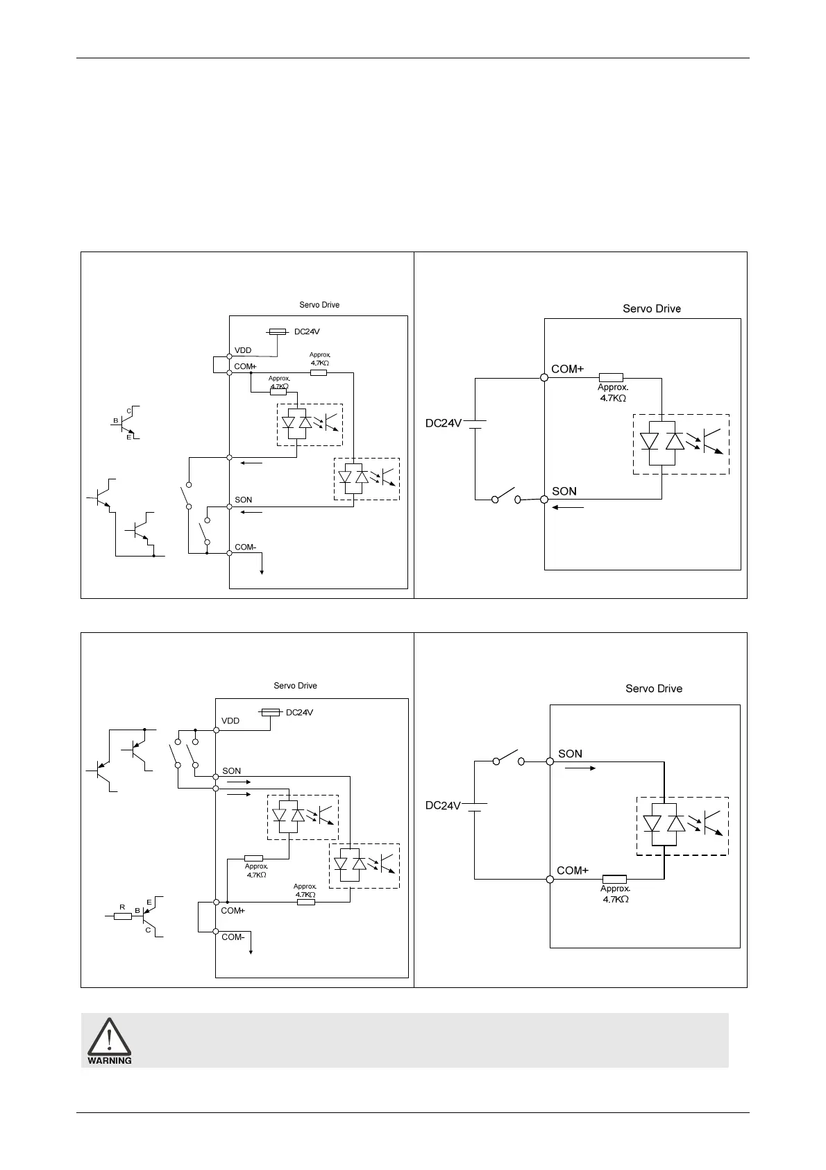
NPN transistor, common emitter (E) mode (SINK mode)
C9: Wiring of DI signal. The servo drive applies to
the internal power.
C10: Wiring of DI signal. The servo drive
applies to the external power.
PNP transistor, common emitter (E) mode (SOURCE mode)
C11: Wiring of DI signal. The servo drive applies
to the internal power.
C12: Wiring of DI signal. The servo drive applies
to the external power.
Caution: Do not apply to dual power or it may damage the servo drive.

Table of Contents

Questions and Answers:

Question and Answer IconNeed help?

Do you have a question about the Delta ASDA-B2 Series and is the answer not in the manual?

Delta ASDA-B2 Series Specifications

General IconGeneral
Control ModePosition, Speed, Torque
Storage Temperature-20°C to 65°C
Position ControlYes
Speed ControlYes
Torque ControlYes
Output Power0.1 kW to 3.0 kW
Communication InterfaceRS-485, CANopen
Encoder FeedbackIncremental
ProtectionOvervoltage, Overcurrent, Overload, Overheat
Operating Temperature0°C to 55°C
Humidity20% to 90% RH (non-condensing)
Vibration Resistance5.9 m/s² (0.6G) at 10-55Hz

Related product manuals