DVP-ES3/EX3/SV3/SX3 Series Hardware and Operation Manual
4-26
*2. If the module is connected to a current signal, the terminals Vn and In+ (n=0–1) must be short-circuited.
*3. If variability in the input voltage results in interference within the wiring, connect the module to a capacitor
having a capacitance between 0.1–0.47 μF and a working voltage of 25 V.
*4. Use shielded cables to isolate the analog output signal cable from other power cables.
*5. If variability in the input loading results in interference within the wiring, connect the module to a capacitor
having a capacitance between 0.1–0.47 μF and a working voltage of 25 V.
*6. The wording “CHX-I” indicates that you can use those five wiring methods for every input channel. The
wording “CHX-O” indicates that you can use those two wiring methods for every output channel.
*7. Use terminals with the same length (less than 200 m) and use terminal resistors of less than 100 ohm.
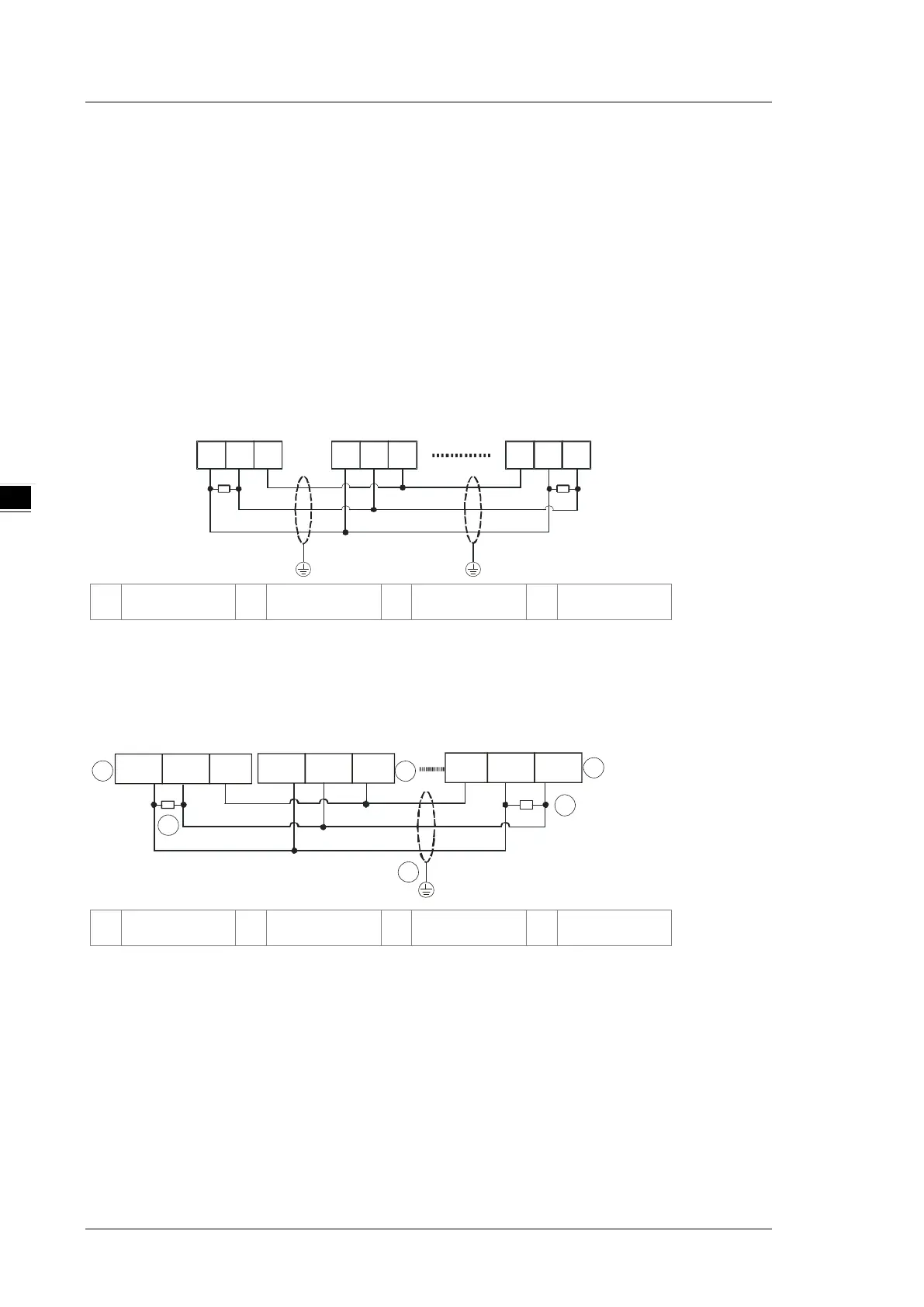
4.1.10 Wiring RS-485 Terminals
D+ D- SG
D+ D- SG SG D+ D-
Master
Slave Slave
Terminal resistor
(120 ohm)
Shielded cable
Shielded cable
①
Master
②
Slave
③
Terminal resistor
④
Shielded cable
Note: Use two-wire shielded cables in a diameter of 20 AWG to ensure a quality communication.
4.1.11 Wiring CANopen Terminals
GNDCAN+CAN-
3
4
1
2
3
GND
CAN+CA N-
2
GND CAN+CAN-
①
Master
②
Slave
③
Terminal resistor
④
Shielded cable
Note:
1. It is recommended to use Daisy Chain for connection and be sure to use 120Ω terminal resistor in
the beginning and the end of the terminal arrangement.
2. GND is the grounding signal for CANopen network.

 Loading...


