DVP-ES3/EX3/SV3/SX3 Series Hardware and Operation Manual
10.2.3 The CAN Interface and Network Topology
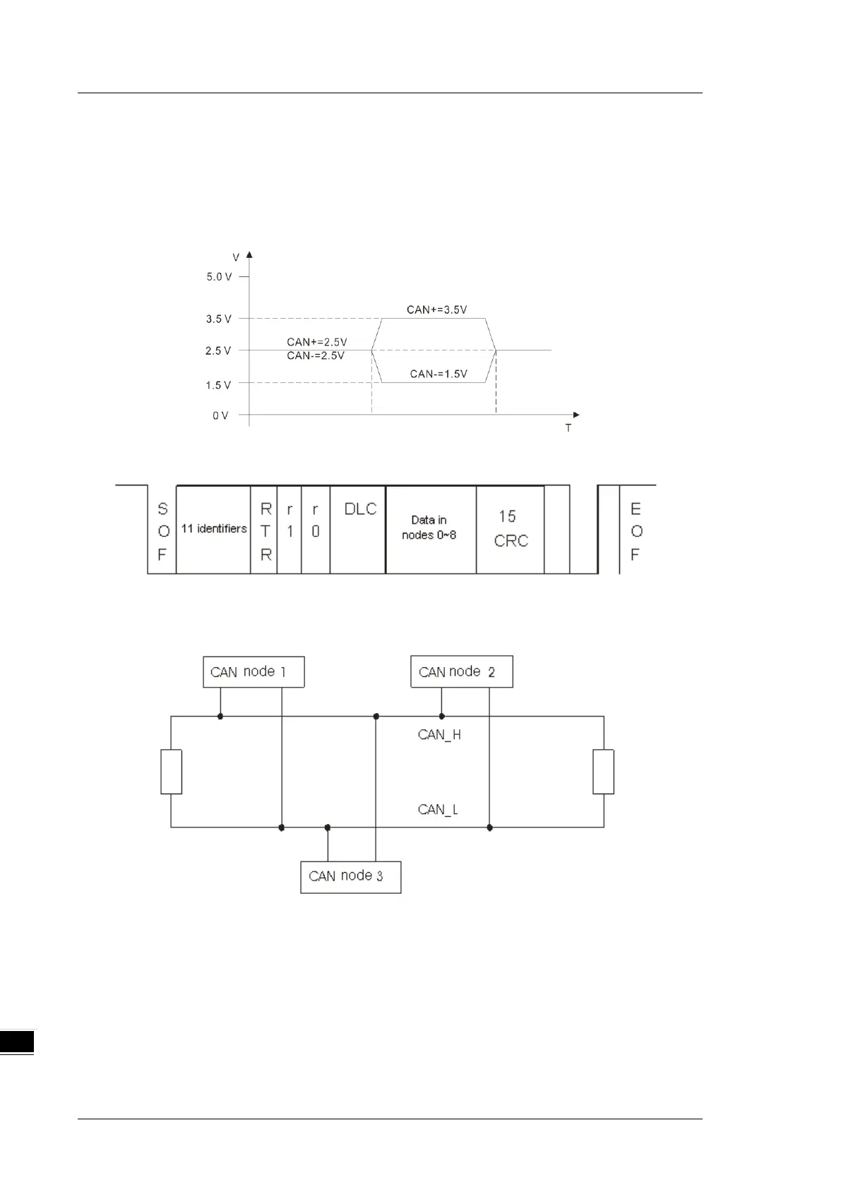
10.2.3.1 Definitions of the CAN Signal and Data Types
The CAN signal is a differential signal. The voltage of the signal is the voltage difference between CAN+ and
CAN-. The CAN+ and CAN- voltages take SG as a reference point. The CAN network can be in one of two
states. One state is a dominant level, and is indicated by the logical “0”. The other state is a recessive level,
and is indicated by the logical “1”. The CAN signal level shows below.
The following picture shows the data frame format. The CAN nodes transmit the CAN messages to the
network from left to right.
10.2.3.2 The CAN Network Endpoint and the Topology Structure
In order to make the CAN communication more stable, the two endpoints of the CAN network are connected
to 120 ohm terminal resistors. The topology structure of the CAN network appears below.

 Loading...


