Chapter 5 CPU and Module Devices
5-19
5.2.12 Data Registers (D)
The data register stores 16-bit data. The highest bit represents either a positive sign or a negative sign, and the values
that the data registers can store range between -32,768 to +32,767.
Two 16-bit registers can be combined into a 32-bit register; for example, (D+1, D) in which the lower number register
represents the low 16 bits. The highest bit represents either a positive sign or a negative sign, and the values that the
data registers can store range between -2,147,483,648 to +2,147,483,647.
Four 16-bit registers can be combined into a 64-bit register; for example, (D+3, D+2, D+1, D) in which the lower
number register represents the lower 16 bits. The highest bit represents either a positive sign or a negative sign,
and the values that the data registers can store range between -9,223,372,036,854,776 to
+9,223,372,036,854,775,807.
You can also use the data registers to refresh the values in the control registers in the modules other than digital
I/O modules. Refer to the ISPSoft/DIADesigner User Manual for more information on refreshing the values in the
control registers.
There are three types of registers.
General-purpose registers: When the PLC changes to RUN, or is disconnected, the value in the register is cleared
to zero. If you want to retain the data when the PLC changes to RUN, Refer to the ISPSoft/DIADesigner User
Manual for more information. Note that the value is still cleared to zero when the PLC is disconnected.
Latched register: If the PLC is disconnected, the data in the latched register is not cleared. In other words, the
value before the disconnection is retained. If you want to clear the data in the latched area, you can use the RST or
ZRST instructions.
Data mapping area for extension modules: When the PLC is connected to a module, the PLC exchanges data with
the connected module at every scan cycle. The data is stored in data registers in PLC CPU and the data will be
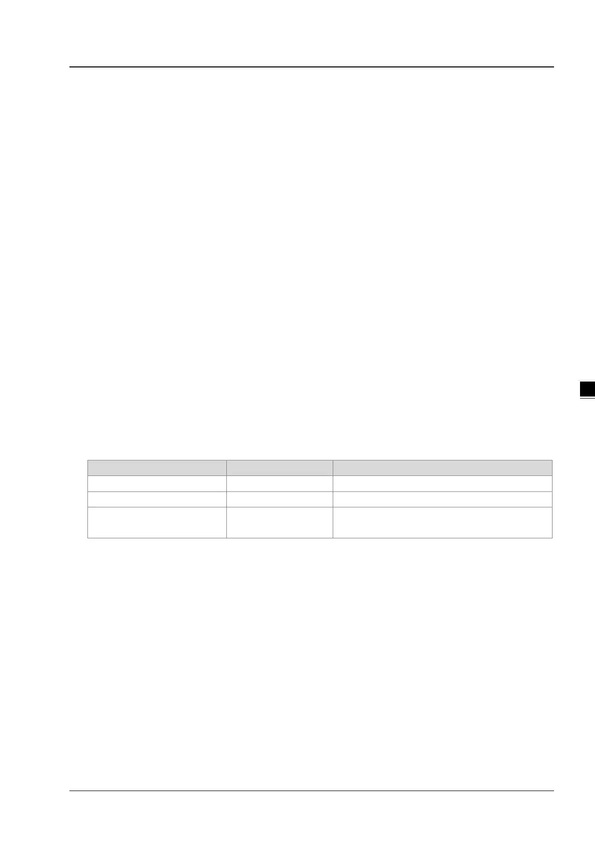
mapped to the control registers (CRs) in the extension modules. Refer to the following table for more details.
Types of extension modules Data mapping areas Remarks
Right-side extension module
Work with SM228 to enable/disable data mapping
Left-side extension module
Work with SM265 to enable/disable data mapping
Left-side DNET/COPM
D16000~D19999
5.2.13 Special Data Registers (SR)
Every special data register has its own definition and specific function. System status and the error messages are stored
in the special data registers. Refer to section 2.2.14 in DVP-ES3/EX3/SV3/SX3 Series Programming Manual for more
reference.
5.2.14 Index Register (E)
The Index register is a 16-bit data register. It is similar to the general register in that data can be read from it and written
to it; however, it is mainly used as the index register. The range of index registers is E0–E9. Refer to section 4.4 in DVP-
ES3/EX3/SV3/SX3 Series Programming Manual for more reference.

 Loading...


