Chapter 9 Ethernet Specification and Operation
9-29
9.4.5 Data Mapping
9.4.5.1 Descriptions on the Data Mapping Page
When the connection between devices is established, you can use data mapping to exchange data between devices.
This section provides an overview of how to create a data mapping table.
Download
Data Exchange
Data Exchange
Set up
Data Exchange
Table
Network View
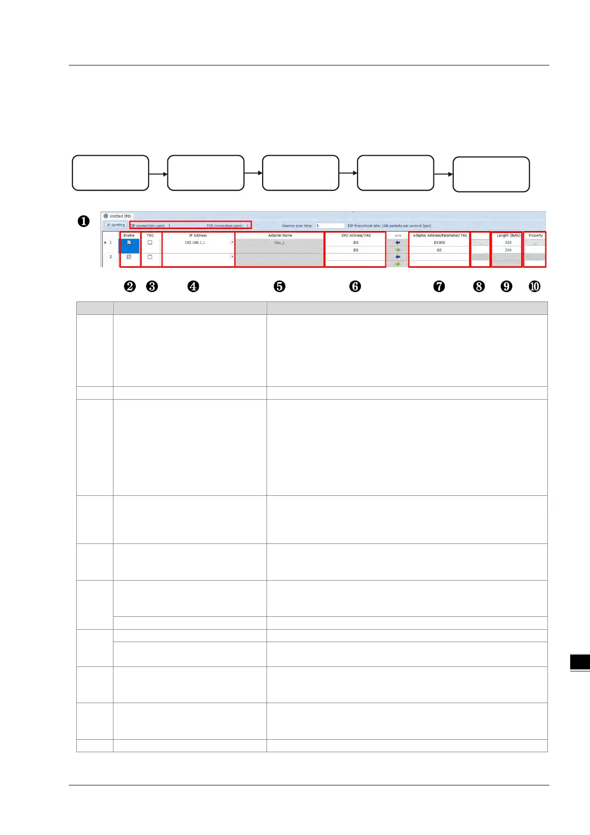
Descriptions for the Data Mapping:
Connection Count
Data mapping connection count; each IP address corresponds to
one independent TCP connection and each row represents one
independent CIP connection. The number of connections cannot
exceed the maximum number of connections for the Scanner. For
the DVP-ES3/EX3/SV3/SX3 PLC CPU, the maximum number of
Enable and disable data mapping for the connection.
TAG
Use TAG to perform data mapping with adapters.
After selecting this check box,
The directional arrow points left of () (READ only)
Registers cannot be used in this row.
The length format is defined by the data format in the Global
Symbols; you cannot change the length format here.
You must create a Consumed TAG in the Global Symbols in
ISPSoft before using this function.
IP address
The IP address of the Adapter to connect to. After the data mapping
connection is established, the system loads the connected device’s
IP address. You can also select the device’s IP address from the list
to add and edit the connection.
Adapter name
Once you select the IP address, its name is displayed but cannot be
modified here. Refer to Section 9.4.3 for more information on
how to change the device name.
CPU register address
Starting address of the data mapping’s register. Devices D and M
are supported. Using device D or device M takes 2 bytes as a unit in
Select the TAG check box.
Select the Consumed TAG name from the list.
Adapter address/parameter
Target adapter’s register address / parameters
Select the TAG check box.
Input the name of the Produced TAG for other connected EIP
devices. The default name is the same as the name shown in .
I/O mapping table
Set up the IN/OUT parameters. When there is no I/O representative
table presented for the Adapter, the parameters cannot be opened,
for example in some PLCs.
Length
Set the data mapping length; unit: byte; the data limit is determined
by EDS file; the maximum is 500 bytes.
You cannot change the length format here when using TAG.
Set the advanced data mapping parameters.

 Loading...


