DVP-ES3/EX3/SV3/SX3 Series Hardware and Operation Manual
4-20
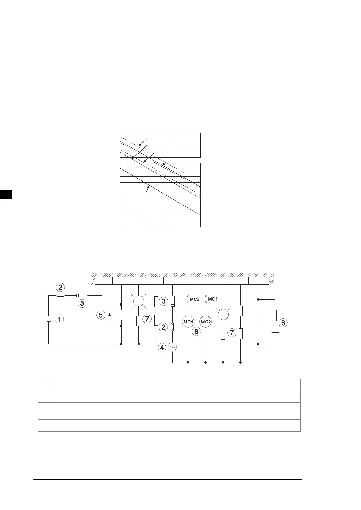
4.1.7.2 Relay Output Circuit
Relay terminals have no polarity. They can be used with alternating current that passes through a load, or with
direct current that passes through a load. The maximum current that can pass through every relay terminal is
2 A, and refer to each product specification for the maximum current that can pass through every common
terminal. The lifetime of a relay terminal varies with the working voltage, the load type (the power factor cosψ),
and the current passing through the terminal. The relation is shown in the life cycle curve below.
Contact Current(A)
20
0.5
0.1
0.2
30
50
0.3 0.7
1 2
200
300
500
100
1000
2000
3000
Operation(X10 )
3
120VAC Resistive
30VDC Inductive(t=7ms)
240VAC Inductive(cos 0.4)
ψ
=
120VAC Inductive(cos =0.4)
ψ
30VDC
Inductive
(t=40ms)
Relay output circuit
Y0 Y1 Y2 C0 Y3 Y4 Y5 Y6 Y7C0
①
Direct-current power supply
②
Emergency: stop using an external switch.
③
Fuse: to protect the output circuit, a fuse having a breaking capacity between 5 A to 10 A is connected
to the common terminal.
④
Alternating-current power supply

 Loading...


