DVP-ES3/EX3/SV3/SX3 Series Hardware and Operation Manual
5-2
5.1 Introduction on CPU Devices
This section describes the values and strings processed by the PLC. It also describes the functions of devices, including
input, output and auxiliary relays, as well as timers, counters, and data registers. The PLC simulates external devices in
the PLC’s internal memory, so the word “device” is a generic name that refers to all the internal memory locations in the
PLC. A device can be a bit device or a word device. Bit devices simulate coils, contacts and flags, while word devices
simulate registers.
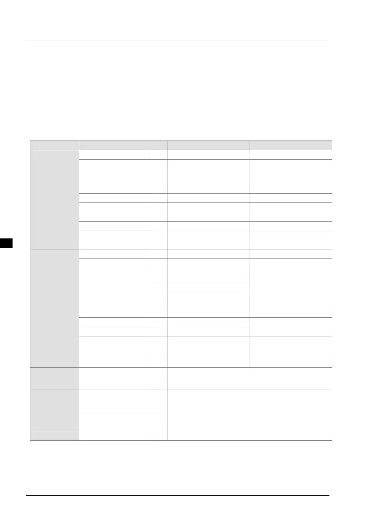
5.1.1 Device Table
Bit device
1
2
Data register
D 48,0000 D0.0–D29999.15
W 48,0000 W0.0–W29999.15*
6
Word device
Input relay X 64 X0–X63
Data register
D 30000 D0–D29999
W 30000 W0–W29999*
6
File register FR 65536 FR0–FR65535
Timer T 512 T0–T511
32-bit counter HC
256(512 words)
HC0–HC255
Index register E
10 E0–E9
5 E10–E14
6
Constant*
3
Decimal system K
16 bits: -32768 to 32767
32 bits: -2147483648 to 2147483647
Constant*
4
Hexadecimal system 16#
16 bit
s: 16#0–16#FFFF
32 bits: 16#0–16#FFFFFFFF
Single-precision floating-
F 32 bits: ±1.17549435
-38
to ±3.40282347
+ 38
5
*1. For DVP-SV3/SX3 series PLC, 16 inputs (X0-X17) and 16 outputs (Y0-Y17) are taken. For DVP20SX3, only 8 inputs
(X0-X7) are taken but since X10-X17 are reserved, the input point for extension is starting from X20.
*2. For DVP-SV3/SX3 series PLC, 16 inputs (X0-X17) and 16 outputs (Y0-Y17) are taken. For DVP28SV3, only 12 inputs
(Y0-Y13) are taken but since Y14-Y17 are reserved, the output point for extension is starting from Y20. For DVP20SX3,
only 6 outputs (Y0-Y5) are taken, but since Y6-Y17 are reserved, the output point for extension is starting from Y20.

 Loading...


