11
6.2.4 Input/Output Interface
Designation: GX2
Plug connector: SUB-D, High Density, 26-pole (bushing)
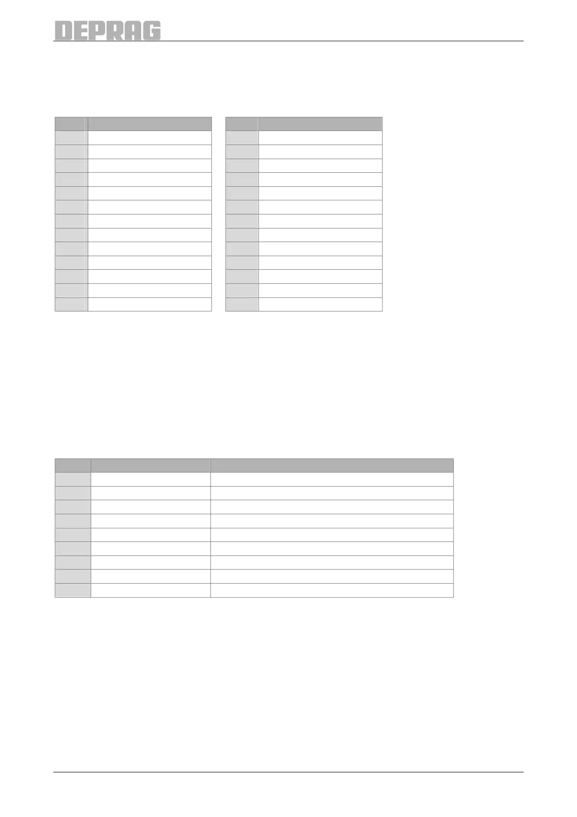
6.2.4.1 Pin Assignment
Pin Designation Pin Designation
1 Start 14 IN6
2 PG0 15 Sys-IO
3 PG1 16 IO
4 PG2 17 NIO
5 PG3 18 Ready
6 PG4 19 OUT1
7 PG5 20 OUT2
8 PG6 21 OUT3
9 IN1 22 OUT4
10 IN2 23 24V_ext
11 IN3 24 Do not connect!
12 IN4 25 GND_ext
13 IN5 26 Do not connect!
6.2.4.2 Power Supply
The I/O module (or component group) of the AST6 must be fed with 24V DC to use the
inputs / outputs. This is done by feeding 24V DC via the pins 23 and 25.
6.2.5 Interface Fieldbus (optional)
6.2.5.1 Profibus
Designation: GX5
Plug connector: SUB-D, 9-pole (bushing)
Pin Designation
1 -- --
2 -- --
3 RX/TX-P Send / Receive data ; data line B
4 PB_RTS
5 PB-GND Mass (Ground)
6 PB-5V Voltage supply +5V
7 -- --
8 RX/TX-N Send / Receive data ; data line A
9 -- --
6.2.5.2 Profinet
Designation: GX5
Plug connector: 2x bushing RJ45
6.2.5.3 Ethernet IP
Designation: GX5
Plug connector: 2x bushing RJ45
6.2.5.4 Ethercat
Designation: GX5
Plug connector: 2xbushing RJ45