User Manual DEV 2194
22 Copyright DEV Systemtechnik GmbH 2013-2017
5.4.4.1 Amplifier
If an amplifier entry is selected on the left side of the Control Tab, the
corresponding panel appears on the right side. It consists of two sections:
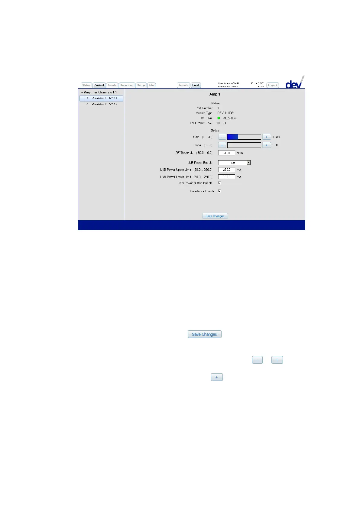
1) In the upper "Status" section first the "Port Number" is shown as a reference to
the index of the SNMP .portTable (please refer to chapter 5.5.4.3.9) and if port
specific error messages are to be identified within the Events Tab
(chapter 5.4.5). In the line below, the "Module Type" is listed (here:
"DEV 11-0081"). Next, the "RF Level" status (red/green) and the measured level
(in [dBm]) are shown. Finally, since the amplifiers provide LNB power with
current monitoring, the "LNB Power Level" status (green, red, or gray) and the
measured current (in [mA] or "off") are indicated.
2) The "Setup" section permits changes on the parameters of the corresponding
amplifier. Note that after settings have been altered within this section in
Local Mode (!), a click on the button is necessary to apply the
changes:
• "Gain" and "Slope" can be adjusted roughly by clicking into the
corresponding control bar, or in discrete steps using the or
buttons. The current target setting is displayed via the (blue/green) colored
bar and via a numerical value next to the button.
• The "RF Threshold" for the RF level monitoring functionality can be
adjusted within a certain range.
• If LNB power is required at the RF input of an amplifier, the drop down list
"LNB Power Enable" needs to be operated. The default is "Off", to turn on
the LNB power, select one of the polarization/band entries:
"HL" (horizontal low: 18 V, 0 Hz), "HH" (horizontal high: 18 V, 22 kHz),
"VL" (vertical low: 13 V, 0 Hz), or "VH" (vertical high: 13 V, 22 kHz).
The current monitoring interval for the current monitoring functionality is
defined by "LNB Power Upper Limit" and "LNB Power Lower Limit". The