User Manual DEV 2194
8 Copyright DEV Systemtechnik GmbH 2013-2017
3 Product Description
With the DEV 2194, DEV Systemtechnik has developed a flexible distribution ampli-
fier chassis that is equipped with two 1:8 distribution amplifiers.
An integrated 1:2 splitter permits the operation of the device as a single 1:16 distri-
bution amplifier instead.
At the front side of the chassis, the 16 female 75 Ohm BNC output ports of the two
distribution amplifiers are located. Additionally, two status LEDs are available here,
please refer to chapter 3.1.1.
The rear side of the device provides seven precision female 75 Ohm F connectors,
used as the input port and as an output monitor port for each of the two amplifiers
and as the input and the two outputs of the integrated 1:2 splitter.
Additionally, each amplifier provides three status LEDs, a push button for LNB
power, and a female 50 Ohm SMA connector to monitor the input signal.
Finally, on the left of the rear side of the chassis, the power inlet and the Ethernet
connector are located.
3.1 Product Features
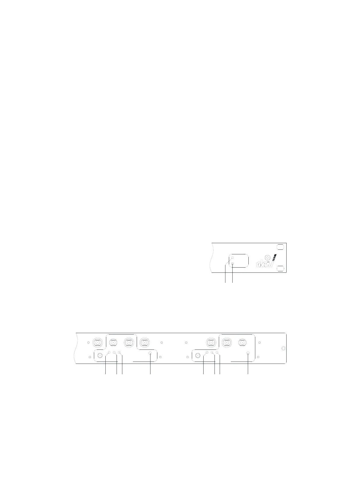
3.1.1 Device Panel
For monitoring purposes, the device provides two status LEDs at the front side and
three status LEDs plus a push button per amplifier at the rear side of the chassis.
The two status LEDs located on the right of the front side are controlled by the
controller of the device:
The green "Operation" LED (3) is off after power on and after a device reset until the
DEV 2194 is operational. If there are pending and not acknowledged error(s), the
red "Alarm" LED (4) is on.
The three status LEDs and the "Bias" (LNB Power) push button of each amplifier are
located on the rear side of the device:
In 1:16
Am plifier 1
Op .
RF
Bias
Bias
O I
Op .
RF
Bias
Bias
O I
Mon In 1:8 Ou t 2 Ou t 1 In 1:8 Mon
Mon Mon
Am plifier 2
7
1310 15 2117189
Operation status LED "Op." (7 & 15)
The LED is on and green if the (corresponding) amplifier is supplied with power
and if the amplifier circuits are working normally. The LED turns to red if circuits
of the amplifier are detected as being defective, i.e. the device has to be sent
to DEV Systemtechnik for repair. If the LED is off, this indicates that no power is
applied to the amplifier.