Field Service Ver. 1.0 Apr. 2005 10. Service Mode
87
ineo 161
ineo 210
Adjustment / Setting
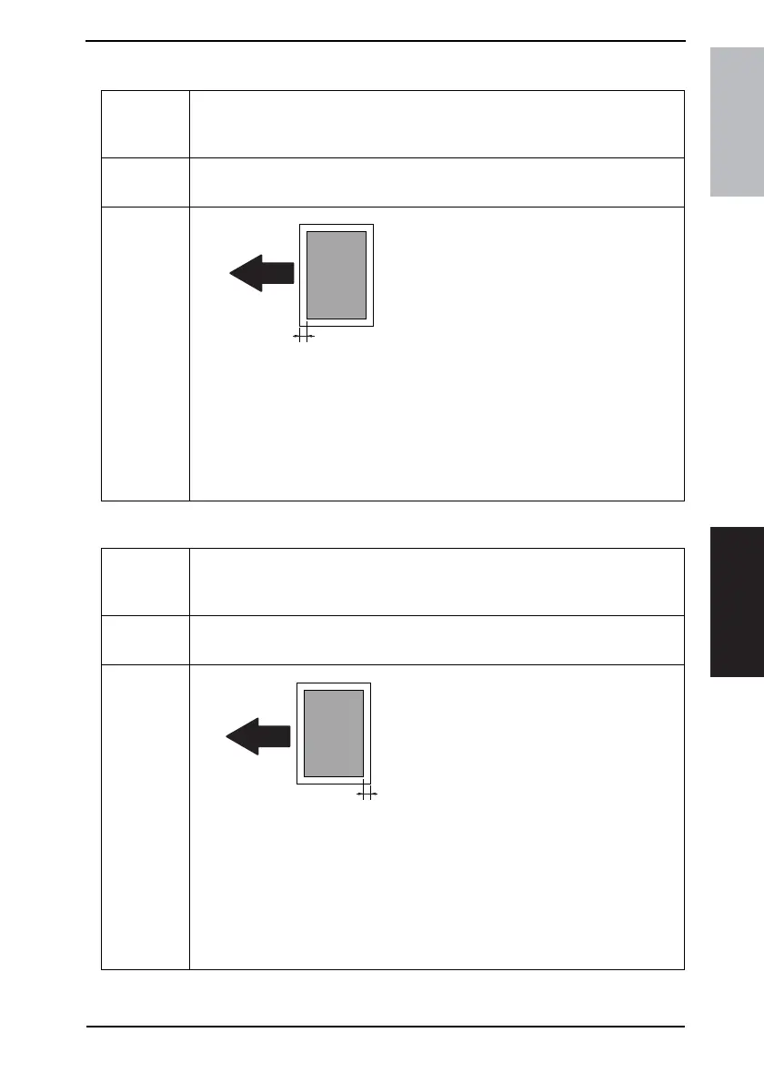
I. LEADING EDGE ERASE
J. TRAILING EDGE ERASE
Purpose/Use To adjust the erase width on the leading edge of the image by varying the laser emis-
sion timing.
✽ When the PH Unit has been replaced
Setting/
Procedure
• The default setting is “4 mm.”
0 mm 1 mm 2 mm 3 mm “4 mm” 5 mm
Adjustment
Procedure
Set the erase width on the leading edge of the
paper (width A).
1. Call Service’s Choice of Service Mode to the screen.
2. Select “Leading Edge Erase” and press the [Yes] key.
3. Using [ ▲ / ▼ ] key, select the desired setting value.
4. Press the [Yes] key to validate the setting value selected in step 3.
Adjustment Instructions
To make the erase width smaller, decrease the setting value.
To make the erase width greater, increase the setting value.
4035D516AA
A
Purpose/Use To adjust the erase width on the trailing edge of the image by varying the laser emission
timing.
✽ When the PH Unit has been replaced
Setting/
Procedure
• The default setting is “4 mm.”
0 mm 1 mm 2 mm 3 mm “4 mm” 5 mm
Adjustment
Procedure
Set the erase width on the trailing edge of the
paper (width B).
1. Call Service’s Choice of Service Mode to the screen.
2. Select “Trailing Edge Erase” and press the [Yes] key.
3. Using [ ▲ / ▼ ] key, select the desired setting value.
4. Press the [Yes] key to validate the setting value selected in step 3.
Adjustment Instructions
To make the erase width smaller, decrease the setting value.
To make the erase width greater, increase the setting value.
B
4035D517AA