- 39 -
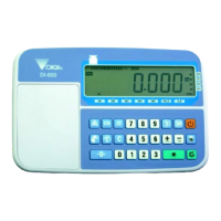
DI-80 USER MANUAL
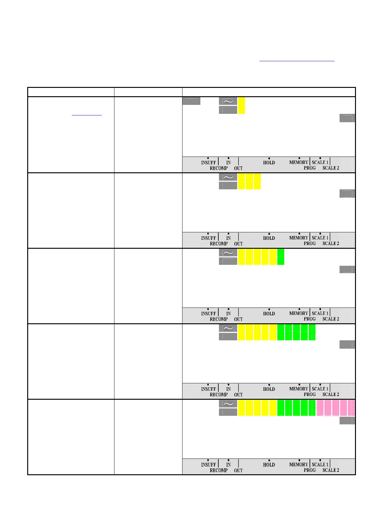
1.14 CHECKER OUTPUT
There are 15 segments of Checker output on the scale. The 1
st
five falls in the YELLOW range, the 2
nd
five falls in GREEN range
while the last five segments falls in RED range which indicate "LOWER", "WITH IN" and 'HIGHER".
User can use the indicator as Weight Checker in Weighing Mode or Quantity Checker in Counting Mode. To use this function,
General Set Point or Individual PLU Set Point must be program in advance. (Please refer to
1.13 General Set Point Setting).
1.14.1 Weighing Mode
For example: Set the General Set Point for Non-PLU items (SPEC 07 bit 1 & 0 set to "1" (Set Point Type is WEIGHT/
WEIGHT)).
OPERATION KEY DISPLAY
¼0»
NET
kg
0. 0 0 0
0. 500> < 1 . 000
T
T
Continued from procedure 5 of
1.13 General Set Point Setting.
When no weight on the
platter, 1
st
segment of Checker
indicator blinking.
Note: Checker Output is not
available in Gross Mode.
NET
kg
0. 2 0 0
0. 500> < 1 . 000
T
1. Place the product on the
platter (Ex. 200g).
The first 3 segments lighter
up.
NET
kg
0. 5 0 0
0. 500> < 1 . 000
T
2. Add 300g of the product on
the platter.
6 segments lighter up and
Set Point Buzzer "On" when hit
the SP-1 range if SPEC 07 bit
set to "1".
Refer to Note 1.
NET
kg
1. 0 0 0
0. 500> < 1 . 000
T
3. Add 500g of the product on
the platter.
NET
kg
1. 0 0 0
0. 500> < 1 . 000
T
4. Add another 500g of the
product on the platter.
Buzzer Off & last segment
of Checker indicator blinking.
All segment of Checker
indicators blinking if scale
Overflow.
Note 1: Buzzer On when weight is within SP-1 and SP-2 or outside SP-1 and SP-2 can be set at SPEC 17 bit 2. Buzzer On
Delay Function when weight < SP-1 when SPEC 17 bit set to "1" can be set at SPEC 02 bit 3, bit 2 & bit 1.
 Loading...