XBee‐PRO®900HP/XBee‐PRO®XSCRFModules
©2014DigiInternationalInc. 133
Repeater Network Configuration
A network may consist of End Nodes (EN), End/Repeater Nodes (ERN) and a Base Node (BN). The base node
initiates all communications.
The repeater network can be configured to operate using Basic Broadcast or Basic Addressed communications.
The addressing capabilities of the modules allow integrators to send a packet as a global packet (DT = 0xFFFF)
and shift out of every radio in the network (Basic Broadcast). Alternatively, the packet can be sent with a
specific DT (Destination Address) parameter so that it is only accepted by a specific remote node (Basic
Addressed).
Configuration Instruction (Basic Broadcast Communications)
Assign each module a unique MY (source) address. (The AM (Auto-set MY) command will configure a unique
source address that is based on module serial number.)
Enable Basic Broadcast Communications (DT = 0xFFFF) or Addressed Broadcast Communications (ATDT
specifies a specific destination)
Configure PK, RO and RB to ensure that RF packet aligns with protocol packet. (ex. PK=0x100, RB=0x100, RO
depends on baud rate).
Configure one or more repeaters in the system (ATMD = 3).
Configure remote nodes as destinations (MD = 4). This will ensure that the remote node waits for the repeater
traffic to subside before it transmits a response.
The configuration instructions above reflect configuration for a Basic Broadcast Repeater system. To configure
a Basic Addressed Repeater system, use the DT (Destination Address) parameter to assign unique addresses
to each module in the network.
Algorithm details
• Packet ID (PID) is composed of transmitting module MY address and packet serial number.
• Incoming packets with a PID already found in the PID buffer will be ignored.
• Each module maintains a PID buffer 8 deep of previously received packets (managed as
FIFO).
Packets may be shifted out the serial port and/or repeated depending on the DT parameter contained in the
RF packet.
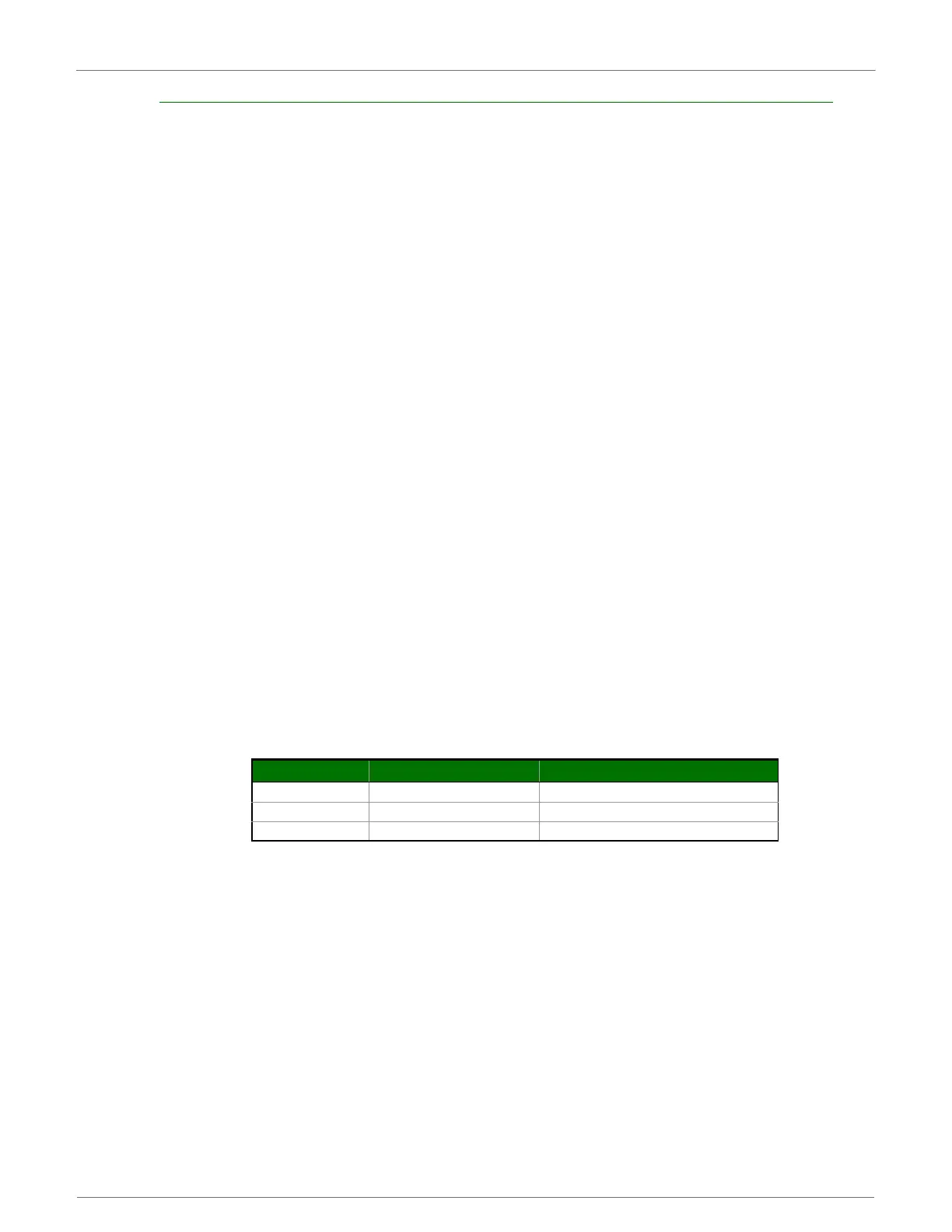
DT(DestinationAddress)parametertruthtable
Repeat delay based on RSSI
A transmitted packet may be received by more that one repeater at the same time. In order to reduce the
probability that the repeaters will transmit at the same instant, resulting in a collision and possible data loss;
an algorithm has been developed that will allow a variable back-off prior to retransmission of the packet by a
repeater. The algorithm allows radios that receive the packet with a stronger RF signal (RSSI) to have the first
opportunity to retransmit the packet.
The RN (Delay Slots) parameter is used to configure this delay. Set RN=0 (no delays) for small networks with
few repeaters or repeaters that are not within range of each other. Set RN=1 for systems with 2 to 5 repeaters
that may be within range of each other.
The actual length of the delay is computed by the formula:
Delay (ms) = L * DS
DS = (-41-RSSI)/10*RN)+RandomInt(0,RN)
Address Match Send out serial port? Repeat?
Global Yes Yes
Local Yes Yes
None No Yes
 Loading...


