XBee‐PRO®900HP/XBee‐PRO®XSCRFModules
©2014DigiInternationalInc. 134
Where L is the length of the transmitted packet in milliseconds, DS is the number of delay slots to wait, RSSI
is the received signal strength in dBm, RN is the value of the RN register and RandomInt(A,B) is a function
that returns a random integer from A to B-0.
Response packet delay
As a packet propagates through the repeater network, if any node receives the data and generates a quick
response, the response needs to be delayed so as not to collide with subsequent retransmissions of the
original packet. To reduce collisions, both repeater and end node radios in a repeater network will delay
transmission of data shifted in the serial port to allow any repeaters within range to complete their
retransmissions.
The time for this delay is computed by the formula:
Maximum Delay (ms) = L * DS
DS = ((-41-(-100))/10)*RN)+RN+1
Where L is the length of the transmitted packet in milliseconds, DS is the number of delay slots to wait, RSSI
is the received signal strength in dBm, and RN is the value of the RN register.
Use Case - Broadcast Repeater Network
Consider modules R1 through R10 each communicating to a PLC using the ModBus protocol and spaced evenly
in a line. All ten nodes are configured as ‘destinations & repeaters’ within the scope of Basic Broadcast
Communications (MD=3, AM, DT=0xFFFF, PK=0x100, RO=0x03, RB=0x100, RN=1). The Base Host (BH)
shifts payload that is destined for R10 to R1. R1 initializes RF communication and transmits payload to nodes
R2 through R5 which are all within range of R1. Modules R2 through R5 receive the RF packet and retransmit
the packet simultaneously. They also send the data out the serial ports, to the PLC's.
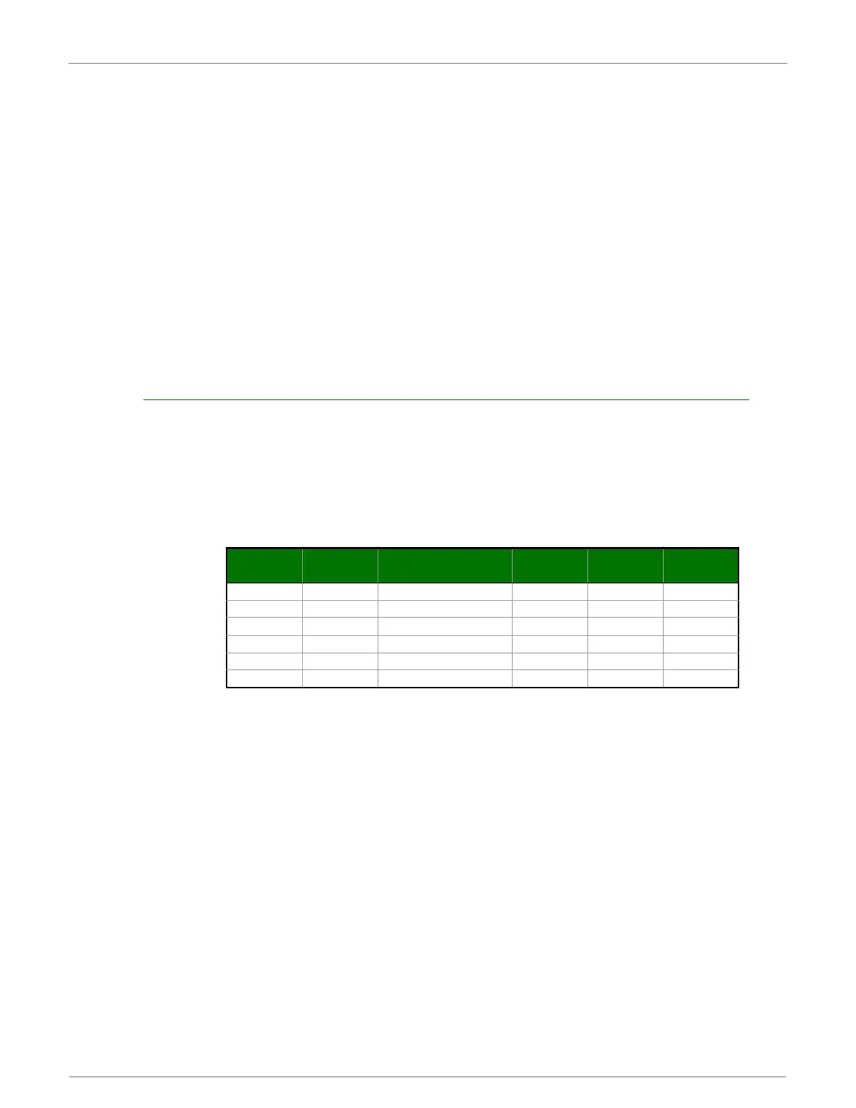
Commandsusedtoconfigurerepeaterfunctions
Bandwidth Considerations
Using broadcast repeaters in a network reduces the overall network data throughput as each repeater must
buffer an entire packet before retransmitting it. For example: if the destination is within range of the
transmitter and the packet is 32 bytes long, the transmission will take approximately 72ms on a 9600 baud
XSC Module. If that same packet has to propagate through two repeaters, it will take 72ms to arrive at the
first repeater, another 72 ms to get to the second and a final 72ms to get to the destination for a total of
216ms. Taking into account UART transfer times (~1ms/byte at 9600 baud), a server to send a 32 byte query
and receive a 32 byte response is ~200ms, allowing for 5 polls per second. With the two repeaters in the path,
the same query/response sequence would take about 500ms for 2 polls per second.
To summarize, this system is sending and receiving 64 bytes 5 times per second for a throughput of 320 bytes
per second with no repeaters and 128 bytes per second with 2 repeaters. Generally, the network throughput
will decrease by a factor of 1/(R+1), with R representing the number of repeaters between the source and
destination.
AT
Command
Binary
Command
AT Command Name Range
# Bytes
Returned
Factory
Default
AM 0x3A (58d) Auto-set MY - - -
DT 0x00 (0d) Destination Address 0-0xFFFF 2 0
MD 0x3C (60d) RF Mode 3-4 1 0
MY 0x2A (42d) Source Address 0-0xFFFF 2 0xFFFF
RN 0x19 (25d) Delay Slots 0-0xFF [slots] 1 0
WR 0x08 (8d) Write - - -
 Loading...


