XBee‐PRO®900HP/XBee‐PRO®XSCRFModules
©2014DigiInternationalInc. 53
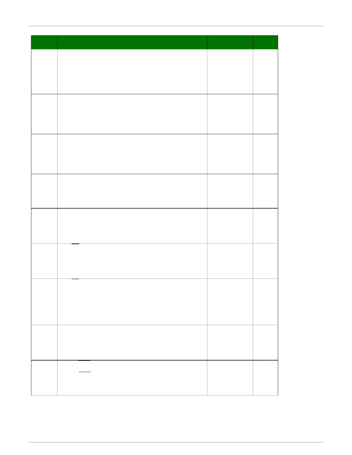
D1
DIO1 / AD1 Configuration (Pin 19).
0 = Disabled
1 = SPI Attention
2 = ADC
3 = Digital input
4 = Digital output low
5 = Digital output high
6 = Uart Data Present Indicator
0-6 0
D2
DIO2 / AD2 Configuration (Pin 18).
0 = Disabled
1 = SPI Clock
2 = ADC
3 = Digital input
4 = Digital output low
5 = Digital output high
0-5 0
D3
DIO3 / AD3 Configuration (Pin 17).
0 = Disabled
1 = SPI Slave Select
2 = ADC
3 = Digital input
4 = Digital output low
5 = Digital output high
0-5 0
D4
DIO4 Configuration (Pin 11).
0 = Disabled
1 = SPI_MOSI
3 = Digital input
4 = Digital output low
5 = Digital output high
0, 1, 3-5 0
D5
DIO5 / ASSOCIATE_INDICATOR Configuration (Pin 15).
0 = Disabled
1 = Associated Indicator
3 = Digital input
4 = Digital output low
5 = Digital output high
0, 1, 3-5 1
D6
DIO6 / RTS
Configuration (Pin 16).
0 = Disabled
1 = RTS flow control
3 = Digital input
4 = Digital output low
5 = Digital output high
0, 1, 3-5 0
D7
DIO7 / CTS
Configuration (Pin 12).
0 = Disabled
1 = CTS flow control
3 = Digital input
4 = Digital output low
5 = Digital output high
6 = RS-485 Tx enable, low TX (0V on transmit, high when idle)
7 = RS-485 Tx enable, high TX (high on transmit, 0V when idle)
0, 1, 3-7 1
D8
DIO8 / SLEEP_REQUEST Configuration (Pin 9).
0 = Disabled
1 = Sleep request
3 = Digital input
4 = Digital output low
5 = Digital output high
0, 1, 3-5 1
D9
DIO9 / ON/SLEEP
Configuration. (Pin 13)
0 = Disabled
1 = ON/SLEEP
output
3 = Digital input
4 = Digital output low
5 = Digital output high
0, 1, 3-5 1
Table5‐09. I/OSettingsandCommands
AT
Command
Name and Description Parameter Range Default
 Loading...


