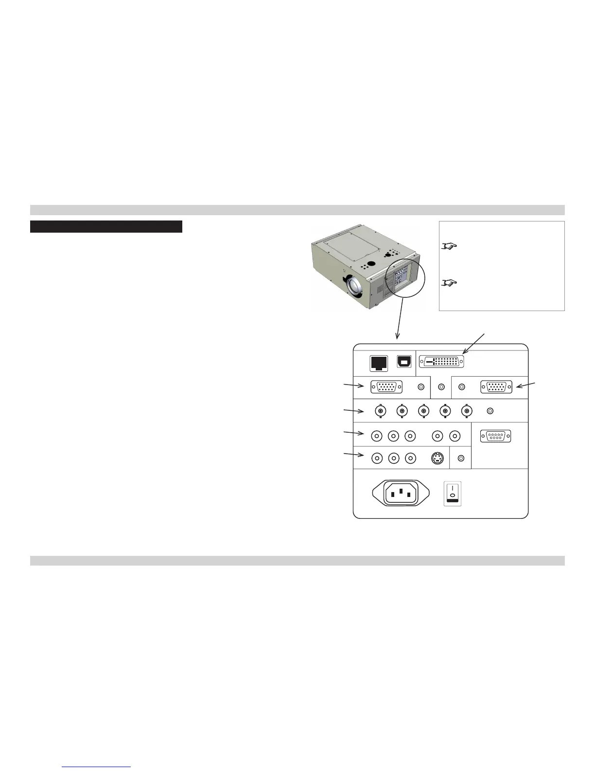
Signal Inputs And Outputs
Computer 1
• Connect an analog computer (VGA) cable to the 15-pin D-type.
• Connect a stereo audio cable to the 3.5mm jack.
Computer 2
• Connect a set of RGsB, RGBHV or YCbCr cables to the BNC connectors.
• Connect a stereo audio cable to the 3.5mm jack.
Computer 3
• Connect a DVI-I cable to the DVI connector.
• Connect a stereo audio cable to the 3.5mm jack below the DVI connector.
Component
• Connect a set of YPbPr or YCbCr cables to the RCA phono connectors.
• Connect a pair of audio cables to the L and R audio connectors or a single audio cable
to the L connector.
Video or S-Video
• Connect a composite video cable to the single RCA phono connector, or an S-Video
cable to the 4-pin mini-DIN.
• Connect a pair of audio cables to the L and R audio connectors or a single audio cable
to the L connector.
Monitor Out
• Connect an analog monitor (VGA) cable to the 15-pin D-type.
• Connect a stereo audio cable to the 3.5mm jack.
COMPONENT
Notes
For a complete listing of pin
congurationsforallsignaland
control connectors, see Wiring
Details later in this Guide.
When Standby Mode is set to Eco:
the Monitor Out connection is
disabled.
COMPUTER 3
COMPUTER 1
COMPUTER 2
VIDEO &
S-VIDEO
MONITOR
OUT
 Loading...