TECHNICAL REFERENCE MANUAL
3.3 Operation modes
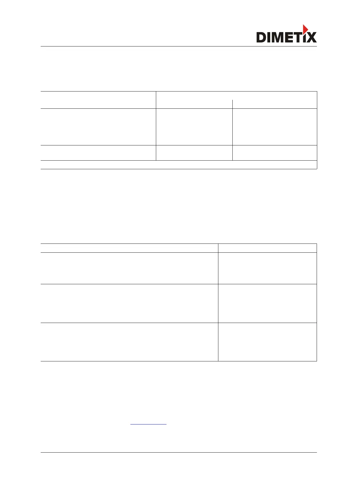
The first decision to be taken is the type of operating mode that will be used to perform distance measurements. While the controlled mode
provides maximum flexibility and accuracy, it is often not suitable for integration into existing drives, PLCs or analog environments. In such
cases the Stand-alone mode might be preferred.
controlled mode stand-alone mode
Auto start Manual start
The measurement is controlled by a host with
commands such as
- sNg
- sNh
- sNuf
The measurement starts after power
on. This must be configured with the
command
- sNA
- sNuA
After configuring the DO1 as DI1, the
measurement can be triggered by an
external signal. Use the following
command
- sNDI
See 9.2 Operation commands starting on page 30 See 9.3.3 Set auto start
configuration (sNA) on page 35
See 9.3.8 Configure digital input (sNDI1)
on page 38
After each measurement all outputs are updated corresponding to the configuration (See 9.3 Configuration commands on page 33).
3.3.1 Controlled mode
In controlled mode, each operation of a DLS-C(H)/FLS-C(H) is triggered by a command sent from a host system over a serial line. While a
single device can be connected to the host system using the RS-232 interface, up to 10 devices can be connected to a single serial RS-422
line. The related command set is described in Chapter 9 on page 29.
3.3.1.1 Configuration
After connecting the module, the steps below are necessary to configure the DLS-C(H)/FLS-C(H) for the controlled interface mode.
No. Action Comment Command
1 Set ID switch Changes to the Device ID are activated after a
power cycle.
Example for device 0:
Change the ID Switch to position 0
Set ID switch to position 0
Power OFF; Wait 10s; Power ON
2
Set controlled mode Set the DLS-C(H)/FLS-C(H) to the controlled
mode, if not already in controlled mode.
Example for device 0:
Set to controlled mode by means of the stop
command.
s0c<trm>
1)
3
Set communication
parameters
If necessary, change the settings for the serial
interface.
Example for device 0:
Set serial interface to 19200 Baud, 8 Bit, no
Parity
s0br+2<trm>
1)
Power OFF; Wait 10s; Change settings on the
host; Power ON
1) Commands are described in 9 Command set on page 29
Note: If the communication parameters of the device are lost, please reset the configuration to the factory settings (8 Factory settings
on page 28) using the reset button (6.2 Reset switch on page 24). Please note that the ID switch must be reset manually.
3.3.1.2 Host software
Host software is required for operation of the DLS-C(H)/FLS-C(H) in controlled mode. When connecting multiple devices to a single serial
line (RS-422), strict Master-Slave communication must be implemented (DLS-C(H)/FLS-C(H) operates as slave). For software sample-code or
application-notes please consult our web site www.dimetix.com.
Careful testing of the host software together with the devices prior to installation is strongly recommended.
Distance Laser Sensor Page 10/53