TECHNICAL REFERENCE MANUAL
4.2.5 Analog / Digital connection
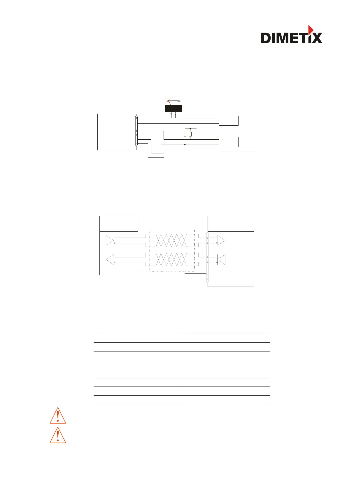
This connection is mainly used with the stand-alone mode. The analog interface of the DLS-C(H)/FLS-C(H) is isolated from the rest of the
device (See 4.2.3 Shield and ground on page 17). When using the analog interface, connect the analog ground (AGND).
Make sure, that the total resistance in the analog path is lower than 500 Ω.
4.2.6 SSI connection
Connect a SSI master according to the connection diagram in Fig. 18. It is compulsory to use a twisted pair cable. See 6.8 SSI output on
page 26 and 6.8 SSI output on page 26 for additional information on the SSI interface.
Typical cable length
The maximum transmission rate depends on the cable length as shown in the following table. For detailed cable specification use the SSI
guidelines. The transmission rate must be specified at the SSI master.
Max. cable length (typical) max. transmission rate (typical)
< 12.5 m < 810 kBaud
< 25 m < 750 kBaud
< 50 m < 570 kBaud
< 100 m < 360 kBaud
< 200 m < 220 kBaud
< 400 m < 120 kBaud
< 500 m < 100 kBaud
The RS-422 interface cannot be used simultaneous with the SSI interface.
The SSI Interface is implemented in the FLS-C(H) only.
Distance Laser Sensor Page 19/53
Fig. 17: Connection of an instrument and a PLC
Fig. 18: Connection of a SSI Master