TECHNICAL REFERENCE MANUAL
2.5 SSI connection
Set the FLS-C(H) in stand-alone mode (3.3.2 Stand-alone mode on page 11) and
connect it to a SSI master as shown in Fig. 6. The measured distances are
immediately available at the SSI output. See 9.3.10 Interface 2 configuration (RS-
422 / SSI) on page 39 for the detailed command description.
Never connect the SSI master before the FLS-C(H) interface 2 is configured as SSI
interface.
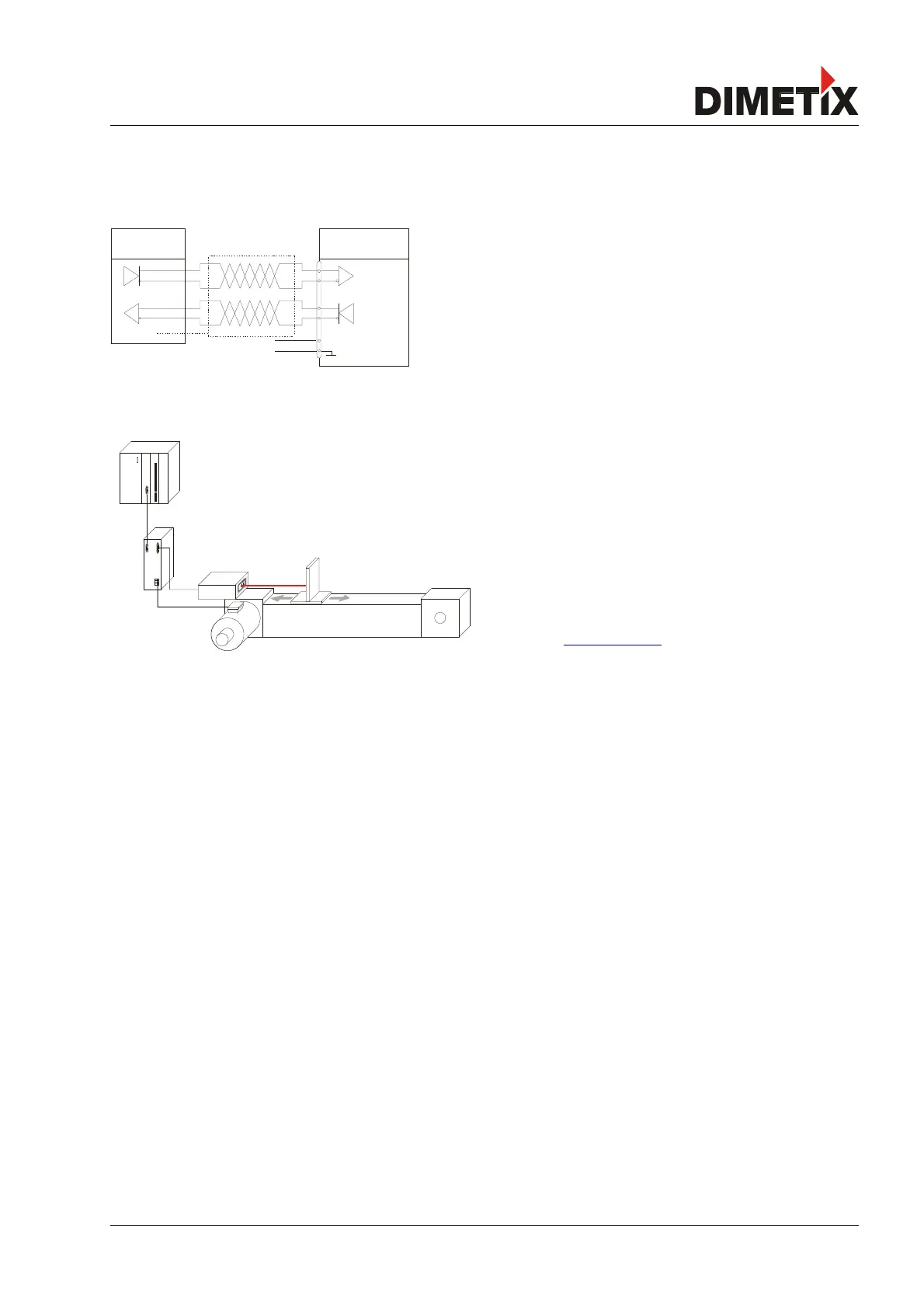
2.6 Positioning
The figure on the left shows a typical positioning application. In this
application the SSI interface of the FLS-C(H) is directly connected to a
position input of a motor drive. The drive controls the motor In such a
way, that the sledge moves to the position given as set point by the
PLC.
The encoder is used for security reasons to double check the movement
by the Drive.
In this applications the FLS-C(H) uses the SSI interface (4.2.6 SSI
connection on page 19) and the moving target characteristic (3.4.2
Moving target characteristic on page 13.
Please check on www.dimetix.com for detailed application notes.
Distance Laser Sensor Page 7/53
Fig. 7: Positioning application
Fig. 6: SSI connection example