TECHNICAL REFERENCE MANUAL
6 Electrical components
To open the side cover, a Torx T9 screwdriver is needed.
6.1 ID switch
This switch is used to set the Device ID and can be set from 0 to 9. The default setting is 0.
6.2 Reset switch
To reset the device to factory settings do the following:
• Change ID Switch to position 0
• Switch OFF the power for the device
• Press the reset button and keep it pressed
• Switch on the power for the device
• Keep the reset button pressed until all LEDs on the device are illuminated
• Release the reset button
• Switch the power OFF and wait 5 seconds
• Switch on the power and wait until the green power LED is on
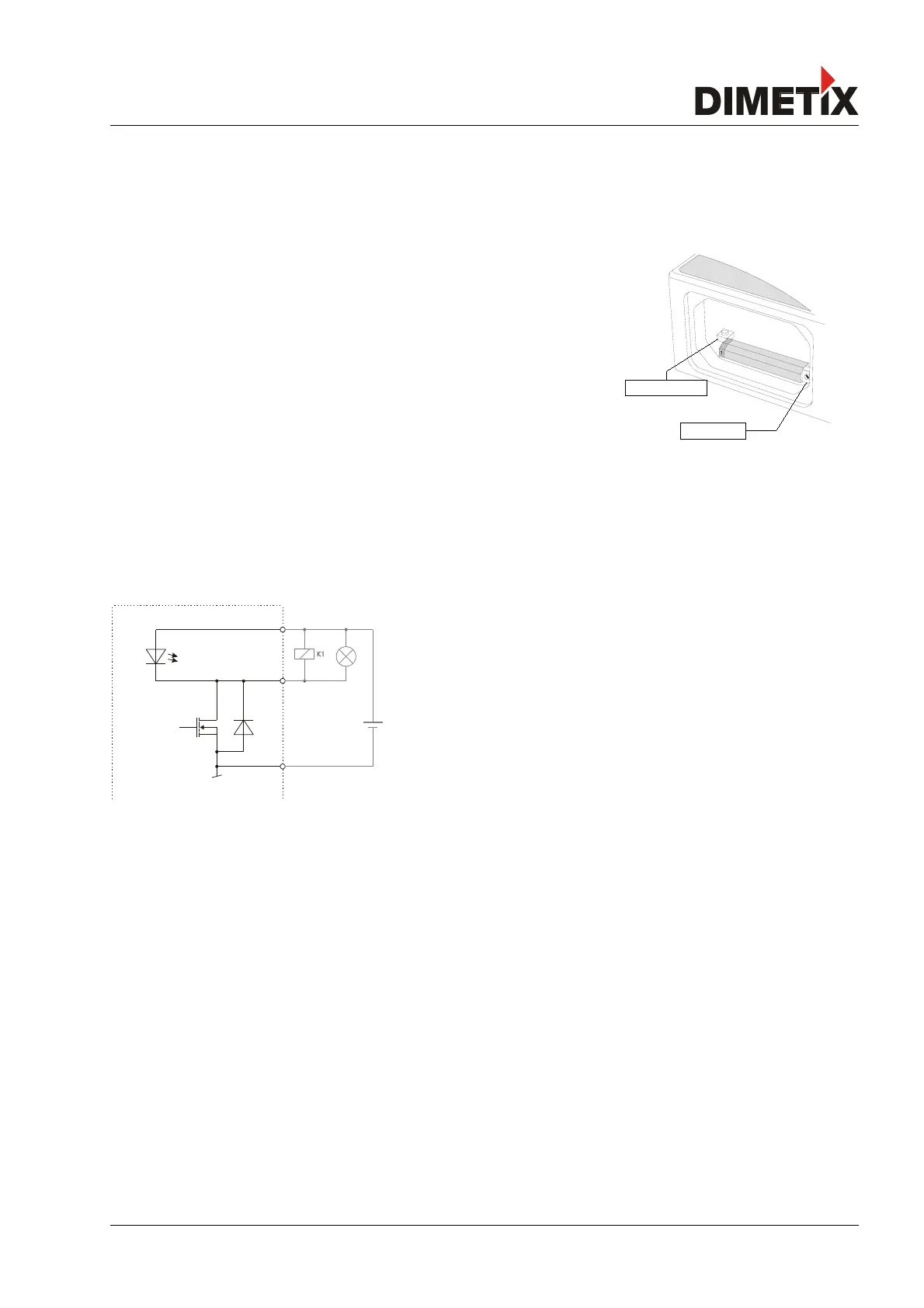
6.3 Digital output
The DLS-C(H)/FLS-C(H) contain two digital outputs for level monitoring (DO 1 and DO 2)
and one digital output for error signalization (DO E). These outputs are open drain
outputs as shown in figure 20 and can drive up to 200mA. Maximum switching voltage
is 30V DC. In the ON state, the FET transistor is electro conductive.
6.4 Digital input
The Digital Output (DO 1) can be configured as a Digital Input (DI 1). This is useful for triggering measurements by means of an external
switch or push button. Please refer to chapter 4.2.7 External trigger connection on page 20.
Low Level is: U
DI1
< 2VDC
High Level is: U
DI1
> 9VDC and U
DI1
< 30VDC
Distance Laser Sensor Page 24/53
ID switch
Reset switch
Fig. 20: Open drain output with external load