TECHNICAL REFERENCE MANUAL
9.3.10 Interface 2 configuration (RS-422 / SSI)
The SSI interface is implemented on the FLS-C(H) device only and deactivated by default. Since the SSI interface uses the same connection
as the RS-422 interface only one of these two interface can be used at the same time.
Use the stand-alone mode with auto start to automatically update the SSI output value.
(9.3.3 Set auto start configuration (sNA) page 35)
Connect the device by RS-232 to do the configuration and use the following commands to activate the SSI interface. See also 4.2.6 SSI
connection on page 19 and 6.8 SSI output on page 26.
Set command Get command
Command
sNSSI+xxx<trm> sNSSI<trm>
Return successful
gNSSI?<trm> gNSSI+xxx<trm>
Return error
gN@Ezzz<trm> gN@Ezzz<trm>
Parameters
N Device ID
xxx binary coded:
Bit0 0: Interface 2 (IF2) functions as RS-422 (SSI is deactivated)
1: Interface 2 (IF2) functions as SSI (RS-422 is deactivated)
Bit1 0: Binary coded data output
1: Gray coded data output
Bit2 0: no error bit output
1: error bit attached to the output data value
Bit3 0: no additional error code output
1: attach 8bit error code (Code -200)
Bit4 0: 24 bit data value
1: 23 bit data value
zzz Error code
Configuration parameters need to be saved (See 9.3.13 Save configuration parameters (sNs) on page 40)
9.3.10.1 Configuration examples
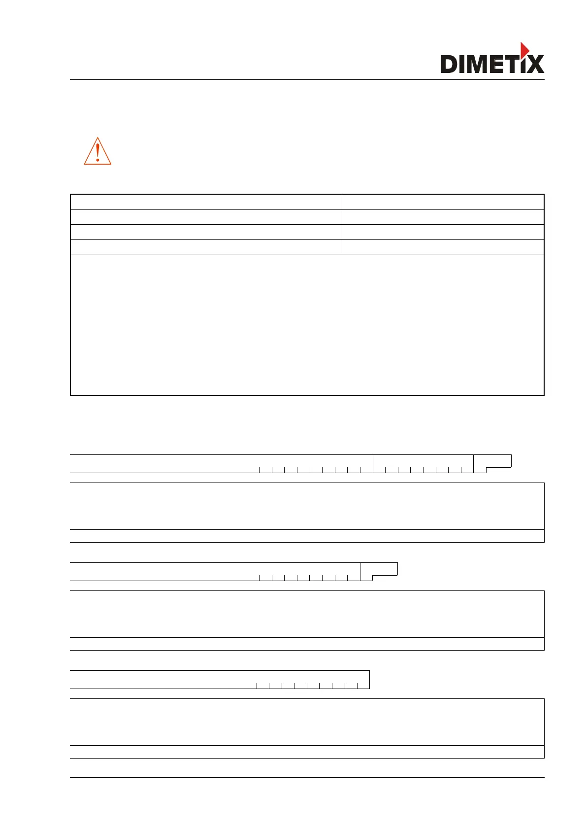
24 Bit data, Error code and Error bit
Data (24 Bit binary) Error code (binary) Error bit
MSB LSB MSB LSB
23 22 21 20 19 18 17 16 15 14 13 12 11 10 9 8 7 6 5 4 3 2 1 0 7 6 5 4 3 2 1 0 0
Configuration:
01101 13→
Bit0 = 1: Interface 2 (IF2) functions as SSI
(RS-422 is deactivated)
Bit1 = 0: Binary coded data output
Bit2 = 1: Error bit attached to the output data value
Bit3 = 1: Attach 8 bit error code (Code -200)
Bit4 = 0: 24 bit data value
Command: sNSSI+13
23 Bit data and Error bit
Data (23 Bit gray) Error bit
MSB LSB
22 21 20 19 18 17 16 15 14 13 12 11 10 9 8 7 6 5 4 3 2 1 0 0
Configuration:
10111 23→
Bit0 = 1: Interface 2 (IF2) functions as SSI
(RS-422 is deactivated)
Bit1 = 1: Gray coded data output
Bit2 = 1: Error bit attached to the output data value
Bit3 = 0: No additional error code output
Bit4 = 1: 23 bit data value
Command: sNSSI+23
24 Bit data
Data (24 Bit binary)
MSB LSB
23 22 21 20 19 18 17 16 15 14 13 12 11 10 9 8 7 6 5 4 3 2 1 0
Configuration:
00001 1→
Bit0 = 1: Interface 2 (IF2) functions as SSI
(RS-422 is deactivated)
Bit1 = 0: Binary coded data output
Bit2 = 0: No error bit output
Bit3 = 0: No additional error code output
Bit4 = 0: 24 bit data value
Command: sNSSI+1
Distance Laser Sensor Page 39/53