TECHNICAL REFERENCE MANUAL
4 Installation
4.1 Mounting
4.1.1 Mounting of the device
Three M4 threaded holes in the bottom of the DLS-C(H)/FLS-C(H) make it easy to mount the device.
Always obey all applicable safety regulations and never use the device outside the specifications stated under 5 Technical data on page 21.
4.1.2 Mounting for the reflective plate
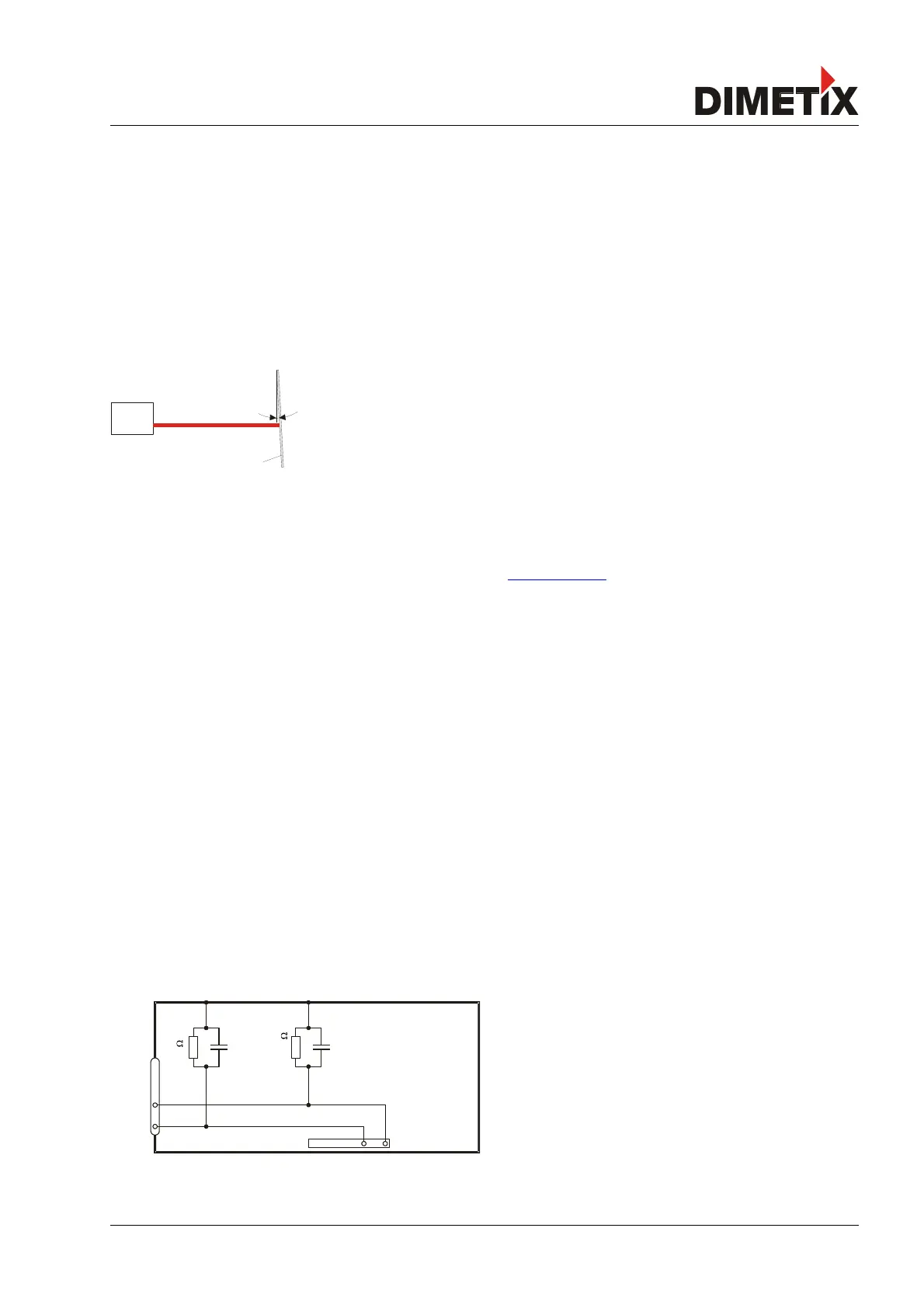
Measuring to the reflective plate may generate erroneous measurements, if the reflective plate is
mounted exactly at an angle of 90° to the laser beam. Therefore mount the reflective plate like shown
in figure 13.
Avoid direct sunlight on the reflective plate to increase measurement performance.
4.1.3 Alignment of the laser beam
Alignment of the laser beam is often difficult when the target is far away, as the laser spot is not visible. An optional telescopic viewfinder
and an alignment jig is available to simplify the alignment procedure. (See www.dimetix.com for additional accessories and further details).
4.1.4 Laser Life time consideration
since the life time of the laser is limited, operate the device in a way, that the laser is switched on only when necessary. The laser life time
stated under 5 Technical data on page 21 relates to the time while the laser is on.
4.2 Device wiring
4.2.1 Power supply
For trouble-free operation use a separate power supply for the DLS-C(H)/FLS-C(H).
FLS-C, DLS-C: 9...30V, 0.5A DC
FLS-CH, DLS-CH: 24...30V, 2.5A DC
4.2.2 Cable connection
A ferrite core must be fitted to the connecting cable. Use a ferrite core with an impedance of 150 Ω to 260 Ω at 25MHz and 640 Ω to 730
Ω at 100MHz. For example you can use KCF-65 from KE Kitagawa.
4.2.3 Shield and ground
The DLS-C(H)/FLS-C(H) contains two electrically isolated grounds, the
general ground (GND) and the analog ground (AGND). GND and
AGND are connected to the housing by a RC element. Please see
figure 19.
Distance Laser Sensor Page 17/53
Fig. 13: Reflective Plate mounting
Fig. 14 Connection between shield and ground