TECHNICAL REFERENCE MANUAL
2 Application examples
Since the configuration of the DLS-C(H)/FLS-C(H) is very flexible the device is usable in various situations. The following application examples
give an idea of possible applications. Please visit www.dimetix.com for a detailed description of the mentioned application examples and
check for additional application examples.
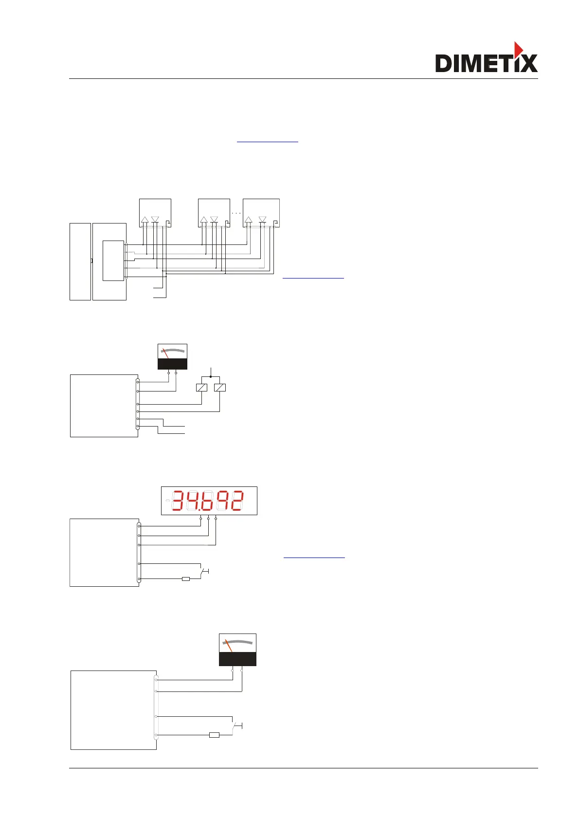
2.1 Serial interface RS-232 / RS-422
While the RS-232 should be used for the configuration of the device (See
3.1 Connection for configuration on page 8) the RS-422 is made for
communication in industrial environment (See 3.3.1 Controlled mode on
page 10 and 4.2.4 Serial connection on page 18).
Fig. 2 shows the connection of multiple DLS-C(H)/FLS-C(H) devices to a
Siemens S7 PLC. A detailed application note can be found on
www.dimetix.com.
For RS-422 connections use twisted pair cables only!.
2.2 Analog and digital output
Activate the stand-alone mode (3.3.2 Stand-alone mode on page 11) and the
device is ready to use. It starts measuring after power on and updates the analog
and digital output according to the configuration. See 9.3.4 and the following
chapters for the configuration commands.
2.3 External display
If Display Mode is enabled, the DLS-C(H)/FLS-C(H) formats the measured distance
as ASCII string, which is understood by External Displays with a serial interface.
Since the DLS-C(H)/FLS-C(H) transfers this formatted string automatically on the
serial interface after completing a measurement. Measurement results can be
displayed on an external display without an additional controller.
Check www.dimetix.com for a detailed application note.
2.4 External trigger
The DLS-C(H)/FLS-C(H) includes the option of triggering measurements with an
external switch or push button on Digital Input 1 (DI 1). Using the Digital Input DI 1
disables the Digital Output DO 1.
Please refer to 3.3.2.2 Manual start configuration on page 11
Distance Laser Sensor Page 6/53
Fig. 5: Use digital input as external trigger
Fig. 4: External display connection
Fig. 2: RS-422 connection to S7 PLC
Fig. 3: AO and DO connection