TECHNICAL REFERENCE MANUAL
6.8 SSI output
The SSI Interface is implemented in the FLS-C(H) only.
6.8.1 SSI Specification
SSI parameters Setting for FLS-C(H)
Distance output values 0.. 16777215 1/10mm (max. 1.67km)
Measurement value coding Binary or gray, MSB first
Transmission mode Configurable, 23/24-bit measurement value, error bit, error code
Resolution 0.1mm
Read out rate ≤ 500Hz
SSI clock rate from controller 83KHz to 1MHz, depending of cable length.
Time lag between two data packets, pause time t
p
> 1ms
Monoflop time, t
m
25μs
Electrical levels, line driver RS-422/485
Cable connection Twisted pair, shielded
6.8.2 SSI Timing
t
m
Monoflop Time: Minimum time to detect the end of transmission. After t
m
, the data line goes to idle state and the slave starts
updating the internal value for the next transmission.
t
p
Pause time: Pause time between two consecutive clock sequences of the master.
The SSI is initially in the idle mode, where the data and clock lines stay HIGH
and the slave keeps updating its internal value.
The transmission mode is evoked when the master initiates a sequence by pulling the clock line to low. Once, the slave receives the
resulting falling edge
at the clock signal line, it automatically stops updating its internal value. With the first rising edge
of the clock
line, the MSB of the sensor’s value is transmitted and with consequent rising edges, the data bits are sequentially transmitted.
After the transmission of the complete data word
(e.g. LSB is transmitted) an additional last rising edge
of the clock sets the clock line
to HIGH. The slave sets or leaves the data line to low and remains there for the time t
m
, to recognize the transfer timeout . If a falling edge
of the clock signal (data-output request) is received within the time t
m
, the same data as before will be transmitted again (multiple
transmission).
If there were no clock pulses within time t
m
, the slave starts updating its internal value after setting the data line to HIGH (idle mode). This
marks the end of a single transmission of a data word. Once the slave receives a clock signal at a time, t
p
(>=t
m
,) the updated position value
is frozen and the transmission of the new value begins as described earlier.
Distance Laser Sensor Page 26/53
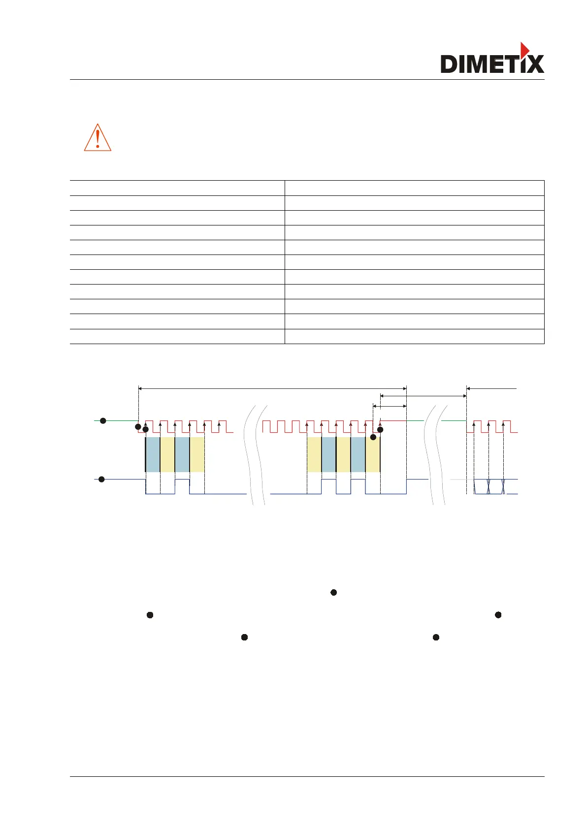
Fig. 21: Timing diagram SSI
clock
pin 5/6
bit 23
bit 22
bit 21
bit 20
bit 3
bit 2
bit 1
data
bit 4
......
2
8
2097152
0
0
0
0
0
0
......
1st data packet transmission
pause time
2nd data packet
t
m
2 3 4 5 6 20 21 22 23 24 25
bit 0
1 2 3
master
slave
monoflop time
t
p
1
1
2
1
3
4
5