27
Optimized layout for A4 print.
1
3
2
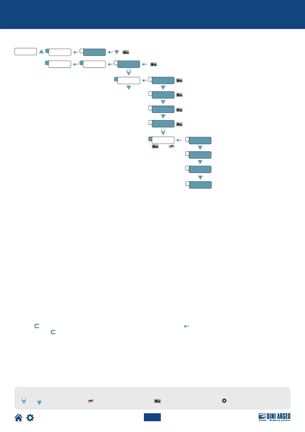
TYPE dep.Ch
A 1
888888
nChanSetup
1C
ConfiG
1
deCi
div
ranGe1
theo.Ca
u.m.
Calib
1
3
4
7
2
5
Cel.sen
Cel.CAp
dead.ld
4
kno.wGt
TECH_MAN_ENG_DGT4X
LEGEND:
Indicates repeated pressing of
the key.
Parameter visible only
under certain conditions.
Parameter or menu subject
to approval.
Default value of the parameter.
Theoretical calibration
Dependent channels
CALIBRATION PROCEDURE:
1. Select mode of use dep.Ch.
2. Set the number of channels used (from 1 to 4).
3. Set the calibration parameters:
deCi = Number of decimals.
u.m. = Unit of measurement (kG, G, t, lb).
div = Minimum division.
ranGe1 = Maximum range.
4. Set the cell data:
sen.Cel = Cell sensitivity (given by the sum of the mV/V value of each cell).
Cel.Cap = Total capacity of the cells (given by the sum of the capacities of each cell).
5. Enter the weight value of the structure in the dead.ld parameter. If you do not know this value, enter “0”.
6. If the structure contains a quantity of material whose weight value is known (e.g. full silo), enter this value in the KNo.WGT parameter.
7. Application of theoretical calibration:
Press the key to exit the calibration menu. The display shows th.Cal?. Press the key to confirm the use of the theoretical
calibration, or the key to cancel.
 Loading...