28
Optimized layout for A4 print.
888888
1
3
4
2
TYPE ind.Ch
A 2
888888
nChan
Chan
Setup
1
2
C
ConfiG
1
deCi
div
ranGe1
theo.Ca
u.m.
Calib
1
3
4
7
2
5
Cel.sen
Cel.CAp
dead.ld
kno.wGt
TECH_MAN_ENG_DGT4X
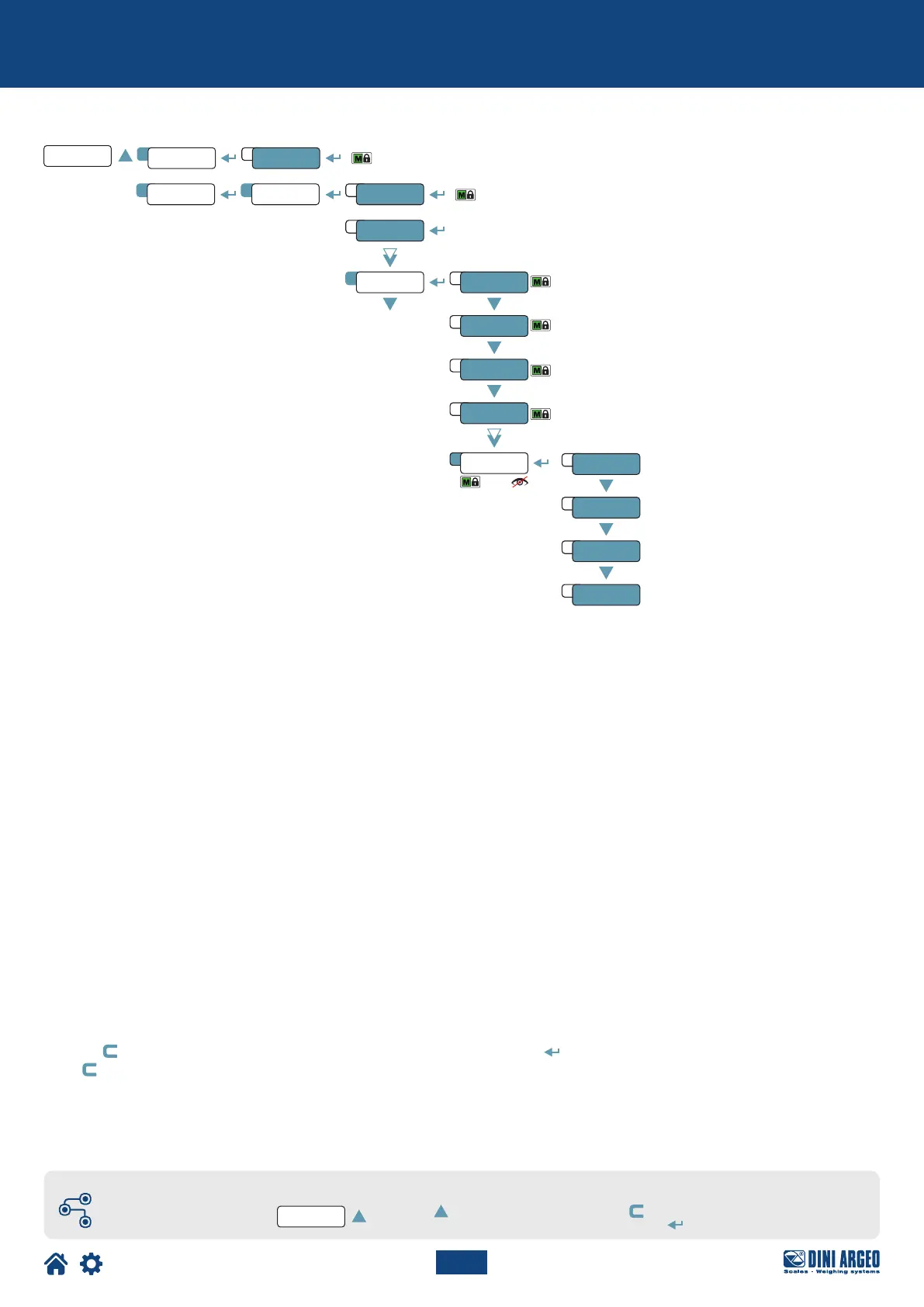
MENU ACCESS:
SAVING THE PARAMETERS:
Press the key during the start-
up procedure.
Press the key several times, until the display shows
SAVE?. Press the key to confirm.
Complete menu
on pages 24 - 25
Theoretical calibration
Independent channels
CALIBRATION PROCEDURE:
1. Select mode of use ind.Ch.
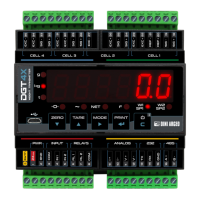
2. Set the number of connected scales (from 1 to 4).
3. Select the scale to be calibrated (from 1 to 4).
4. Set the calibration parameters:
deCi = Number of decimals.
u.m. = Unit of measurement (kG, G, t, lb).
div = Minimum division.
ranGe1 = Maximum range.
5. Set the cell data:
sen.Cel = Cell sensitivity (given by the sum of the value of each cell).
Cel.Cap = Total capacity of the cells (given by the sum of the value of each cell).
6. Enter the weight value of the structure in the dead.ld parameter. If you do not know this value, enter “0”.
7. If the structure contains a quantity of material whose weight value is known (e.g. full silo), enter this value in the KNo.WGT parameter.
8. Application of theoretical calibration:
Press the key to exit the calibration menu. The display shows th.Cal?. Press the key to confirm the use of the theoretical calibration,
or the key to cancel.
9. Repeat the procedure from point 3 for each scale to be calibrated.
 Loading...