57
Optimized layout for A4 print.
TECH_MAN_ENG_DGT4X
Modbus Protocol
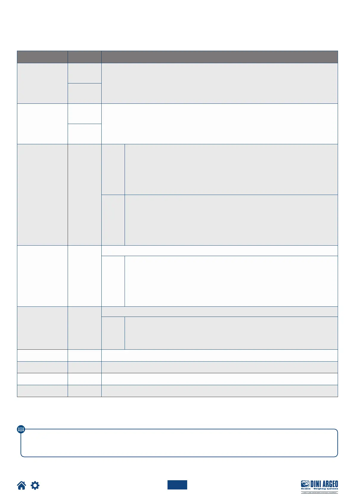
MODBUS REGISTERS FOR DATA READING SINGLE SCALE
Data Register DESCRIPTION
Gross Weight
30001
Gross weight value.
30002
Net Weight
30003
Net weight value.
30004
Input status
register
30005
Bit 15
(msb)
Bit 14
Bit 13
Bit 12
Bit 11
Bit 10
Bit 9
Bit 8
(lsb)
Active channel.
Active channel.
No function.
No function.
No function.
No function.
Input no. 2 status.
Input no. 1 status.
Bit 7
(msb)
Bit 6
Bit 5
Bit 4
Bit 3
Bit 2
Bit 1
Bit 0
(lsb)
Gross zero zone (0 = “outside zone 0”; 1 = “in zone 0”).
Tare PT (1 = a preset tare is active).
Tare (1 = a tare is active).
Overload condition (0 = No; 1 = Overload).
Underload condition (0 = No; 1 = Underload).
Stability (0 = Unstable; 1 = Stable).
Gross weight sign (0 = “+”; 1 = “-”).
Net weight sign (0 = “+”; 1 = “-”).
Command status
register
30006
Last command received.
Bit 7
(msb)
Bit 6
Bit 5
Bit 4
Bit 3
Bit 2
Bit 1
Bit 0
(lsb)
Last command result.
Last command result.
Last command result.
Last command result.
Processed command count.
Processed command count.
Processed command count.
Processed command count.
Output status
register
30007
No function.
Bit 7
(msb)
...
Bit 2
Bit 1
Bit 0
(lsb)
No function.
...
No function.
Digital output 1 status (0 = OFF; 1 = ON).
Digital output 2 status (0 = OFF; 1 = ON).
µV Channel 1
30111 µV of channel 1.
µV Channel 2
30112 µV of channel 2.
µV Channel 3
30113 µV of channel 3.
µV Channel 4
30114 µV of channel 4.
This manual contains the main registers for reading data / sending commands.
Refer to the Modbus protocol manual for a complete list of available registers.
 Loading...