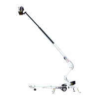
DINO 210XT
13
OPERATION OF SAFETY DEVICES
1. Support outriggers (Fig. A)
The safety limit switch RK3 prevents the operation of the outriggers and the driving device when
the boom does not rest on the transport support. The switch is located on the tow-bar at the transport
support.
2. Lifting the boom (Fig. B)
All the lift’s support outriggers must be in the support position before the boom is lifted. Make sure
that the wheels are off the ground.
The safety limit switches RK11, RK12, RK13 ja RK14 are located on the support outriggers.
3. Overload protection switches (Figs. A and C)
The safety limit switches prevent overloading of the lift. At a predetermined position the overload
limit switch RK4 stops extension of the telescope and lowering of the boom.
The overload limit switch RK5 backs up if the RK4 for some reason does not work.
The green light in the platform control centre is lit when the platform is inside the allowed operating
range. The red light comes on as the RK4 stops the movement. When the red light is on, the lift can
be operated in the direction where it stays inside the allowed outreach area. The safety limit switch
RK5 backs up the operation of the RK4 by switching on the buzzer on the platform.
4. As the emergency stop button is depressed all movements stop and the power unit is turned
off.
The emergency stop pushbutton must be pulled up before the power unit can be restarted
(button 3 on page 14 and button 22 on page 18).
Ensure the operation of the safety devices - do not lock the chassis panel cover with key while
the lift is in operation.