DINO 210XT
92
ADJUSTMENT VALUES OF MOVEMENT
SPEEDS
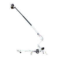
1. Measuring devices required for the adjustment
− volt-ohm-milliammeter (for measuring of
current)
− measuring adapter (for measuring of current)
2. Disconnect the socket from the control card and
connect the measuring adapter between the
valve and the socket.
3. Connect the measuring conductors to the direct
current range of the volt-ohm-milliammeter
(max. measuring current I
max
=2A)
Lift up the machine from the ground using the outriggers for operating the boom
4. Turn the key-switch to position 3, the power unit may be switched off
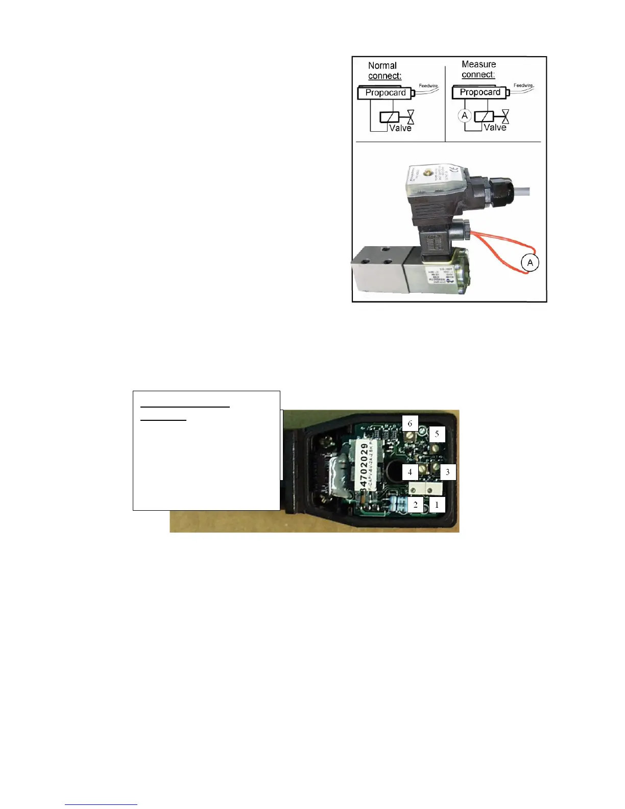
5. Check that the adjustable resistors TR9, TR10, TR11 and TR12 on the circuit card in the
main centre have been turned counter-clockwise to their extreme positions
6. Frequency adjustment (the lift in boom-mode, the power unit is not running)
Turn at first the adjustment screw 3 on the control card to its minimum position (to
extreme position counter-clockwise) and after this turn it 1/4 turn clockwise.
7. Intensity adjustment of frequency (the lift in boom-mode, the power unit is not running)
Turn at first the adjustment screw 4 on the control card to its minimum position (to
extreme position counter-clockwise) and after this turn it 1/4 turn clockwise.
8. Adjustment of the ascending ramp (the lift in boom-mode, the power unit is not running)
Turn at first the adjustment screw 5 on the control card to its minimum position (to
extreme position counter-clockwise) and after this turn it 1/5 turn clockwise.
9. Adjustment of the descending ramp (the lift in boom-mode, the power unit is not running)
Turn the adjustment screw 6 on the control card to its minimum position (to extreme
position counter-clockwise), the descending ramp is not in use.
CONTROL CARD
SCREWS
1. Maximum current I
max
2. Minimum current I
min
3. Frequency adjustment
4. Intensity of frequency
5. Ascending ramp
6. Descending ramp