F6300 Power System Simulator User Guide
72A-2337-01 Rev. B 11/05 4-5
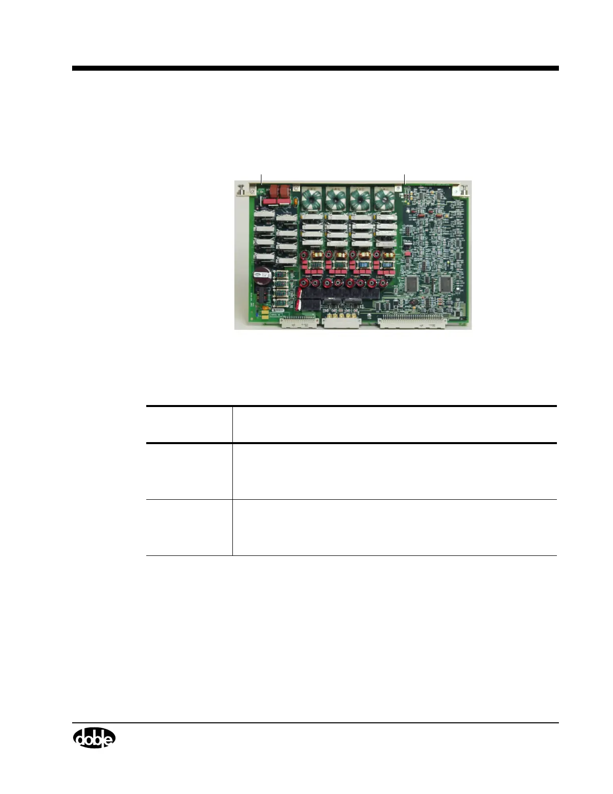
Current Amplifier Circuit Boards
Six current amplifier boards are installed in slots 5-10. Each current amplifier circuit board has
two LEDs that are visible when looking at the front of the board (
Figure 4.3).
SRC ON LED
350 V LED
Figure 4.3 Current Amplifier Circuit Boards
Table 4.1 defines the function of the LEDs.
Table 4.1 Current Amplifier Circuit Boards LEDs
Amplifier
Board LED
Indication
350V Illuminates steady green after the Power up diagnostics pass, indicating a
healthy status.
This LED is located on the left side of the board, close to the top edge, as
viewed with the front panel oriented towards the front.
SRC ON
(right
side *)
Illuminates steady green when the amplifier is enabled or turned on by
ProTesT software, indicating an active source.
This LED is located on the right side of the board, close to the top edge,
as viewed with the front panel oriented towards the front.
* If the 350V LED is not illuminating green, replace the amplifier circuit board. Refer to Chapter
5 ”Field Replacement Procedures”.
If all 6 350V LEDs are off, check the power supply. Refer to ”Checking the Power Supply”
on page 4-10.