Removing and Replacing the Communications Board
5-8 72A-2337-01 Rev. B 11/05
Removing and Replacing the Communications Board
The communications board supports the input and output terminals on the right side of the front
panel. To replace the communications board, first remove the instrument front panel, but do not
disconnect the leads from the circuit breaker on the left side of the panel.
1. Remove the front panel using the procedure in ”Remove and Replace the Instrument Front
Panel” on page 5-4 to access the Communications board.
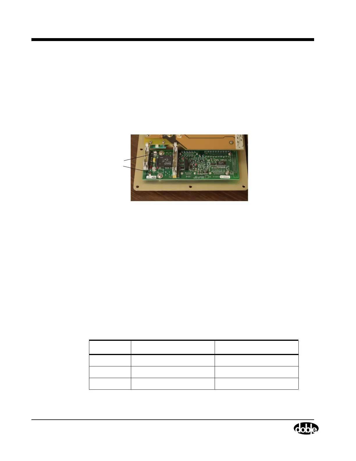
2. Remove the two Phillips head screws that secure the communications board to the front
panel (
Figure 5.9).
Phillips
Screws
Screws
Figure 5.9 Communications Board Screws
3. Tilt the front panel up until it leans against the instrument.
4. Use an open-ended wrench or pliers to remove the eight nuts on the right side of the front
panel (two for each of the four connectors).
5. Tilt the front panel back down until it lies face down on the table.
6. Lift the communications board off the front panel.
7. Place the new communications board in its position on the right side of the front panel.
8. Secure the communications board to the front panel with the two Phillips head screws.
9. Use an open-ended wrench or pliers to turn the 8 nuts on the front of the front panel.
10. Tilt the front panel back into place. Be sure the High Current Interface at the bottom of the
front panel mates properly with the connector on the motherboard.
11. Secure the front panel to the instrument chassis with the 12 hex-head screws.
12. Reconnect wires W2, W3, W4, W5, W6, and W7 (Table 5.2).
Table 5.2 W2, W3, W4, W5, W6, and W7 Connections
Wire Connects From Connects To
W6 Communications board CPU board
W7 Communications board Analog I/O board
W20 Analog Multiplexer board Output Terminal board
13. Replace the instrument cover.