F6300 Power System Simulator User Guide
72A-2337-01 Rev. B 11/05 2-5
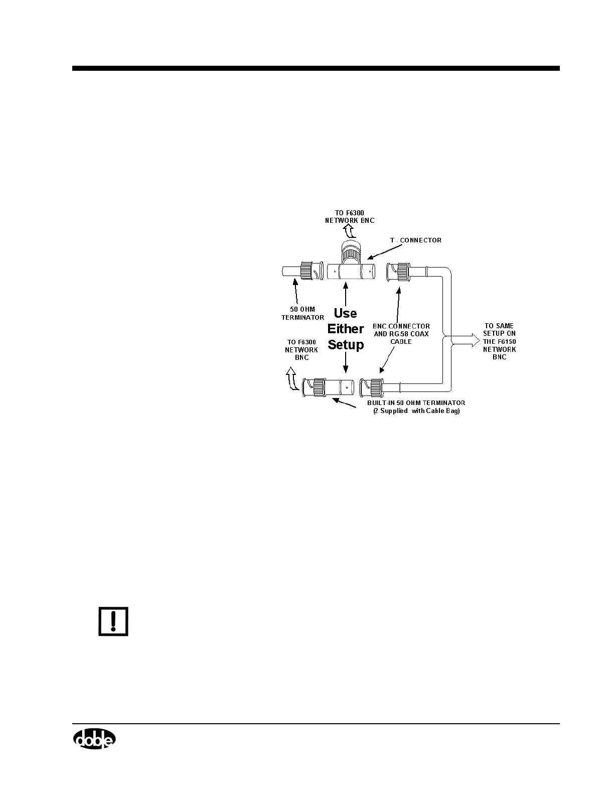
Ethernet 10Base 2 Communication using Terminators
To connect your F6150 and F6300 for serial communication (Figure 2.3):
1. Connect one of the 50 Ohm terminator to the F6150 network BNC connector.
2. Connect the second 50 Ohm terminator to the F6300 network BNC connector.
3. Connect the supplied RG-58 coax cable to both the F6150 and the F6300.
Figure 2.3 A Terminating 10Base2 Connection
Ethernet Communication to F6000 Instruments
The configurations for Ethernet communication include:
• Computer to CPU1 F6150
• Computer to CPU2 F6150 with Switch/Hub
• Computer to CPU2 F6150 with CAT5 Crossover Cable
• Computer to CPU1 F6150/CPU1 F6300
• Computer to CPU2 F6150/CPU2 F6300
• Computer to CPU1 F6150/CPU2 F6300
• Computer to CPU2 F6150/CPU1 F6300
NOTE F6150 to F6300 Low voltage cable connections are not shown.
Table 2.1 lists the Ethernet communications setup parameters. Figure 2.4 through
Figure 2.10 on page 2-9 shows the configurations.