Perform a Power Up and a Visual Check to Identify a Faulty Component
5-4 72A-2337-01 Rev. B 11/05
Perform a Power Up and a Visual Check to Identify a Faulty Component
Perform a power up and a visual check:
1. Attach the power cord to the instrument and turn it on.
2. Observe the LEDs on the left side of each amplifier board:
• A green light indicates that the board is working properly.
When the sources are active, the green LED on the right side of an amplifier board
illuminates when that particular amplifier is supplying power.
• No light indicates a faulty amplifier board.
3. Verify, through the audible sound, that the four cooling fans are operating.
Remove and Replace the Instrument Front Panel
Remove the front panel of the instrument:
1. Remove the 12 hex-head screws from the front panel (Figure 5.4).
2. Disconnect W6, W7, and W20, from the CPU board and the Analog Multiplexer board.
3. Rest your fingers on the inside surface of the front panel and grasp the top of the black
instrument frame.
4. Push the panel forward and swing the panel to the side.
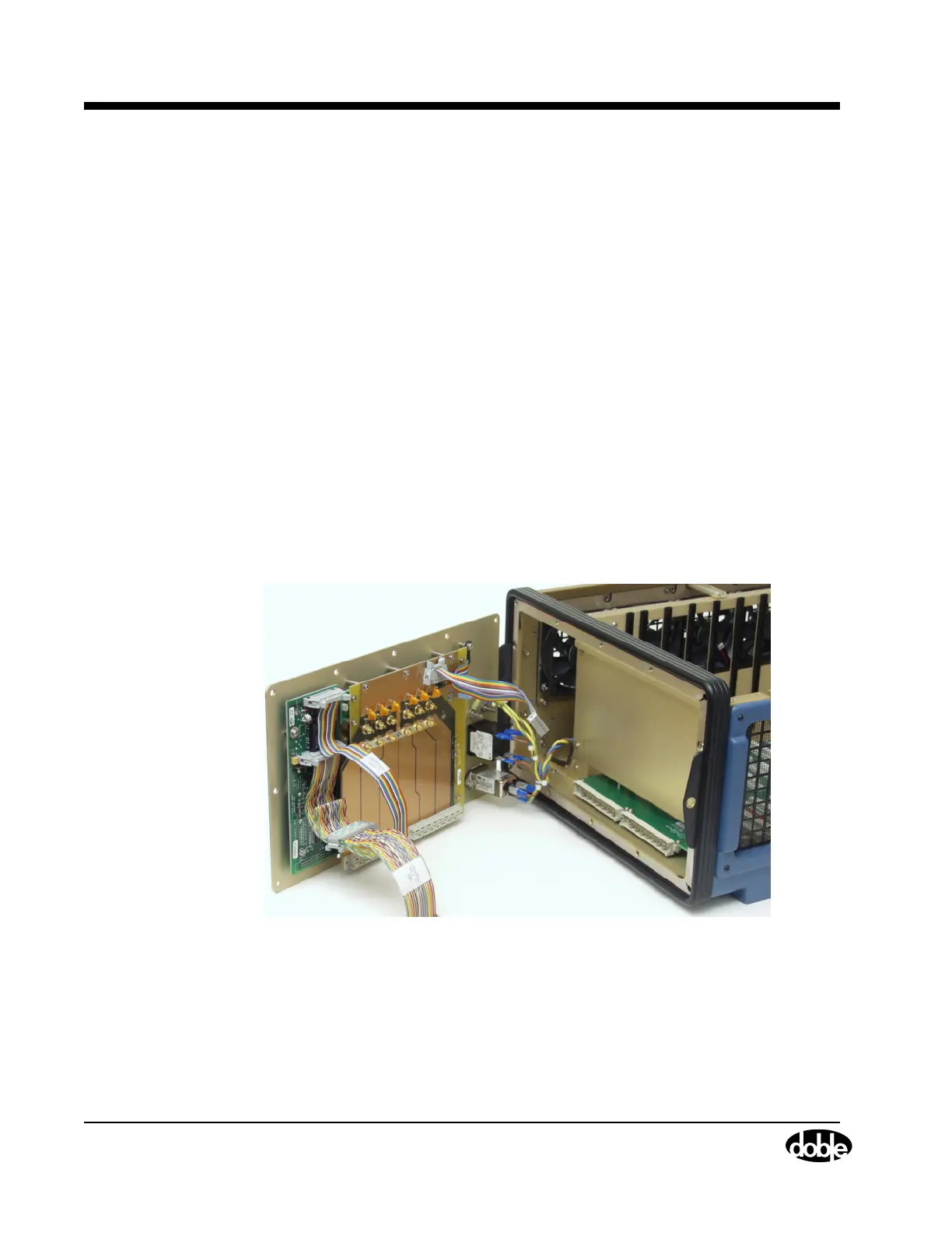
Figure 5.4 F6300 with Front Panel Swung to Side
5. Gently lift the front panel away from the instrument and lay the front panel face down on the
table in front of the instrument. A High Current Interface connects the lower part of the
Output Terminal board to the motherboard. Carefully work this connection loose as the front
panel tilts away from the chassis frame