F6300 Power System Simulator User Guide
72A-2337-01 Rev. B 11/05 5-5
.
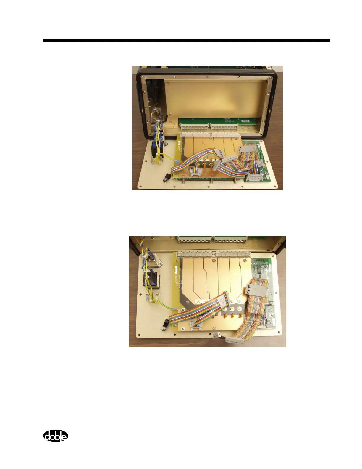
Figure 5.5 F6300 with Front Panel Removed
6. Disconnect wires W20 from the Output Terminal board.
7. Disconnect wires W6 and W7 from the communications board and set them aside for use
with the new front panel.
Figure 5.6 W6 and W7 Wires Disconnected
8. Disconnect the blue and brown AC wires that lead from the circuit breaker back to the
instrument.
• Grasp the blue insulation.
• Pull hard and work the connectors loose.
9. Use an open-ended wrench to remove the hex nut that secures the chassis ground wire to
the circuit breaker.