72A-2337-01 Rev. B 11/05 3-1
3. Setup and Configuration
This chapter explains how to set up the F6300 Instrument and how to establish communications
between the instrument and the software used to control it. It also explains briefly how to
configure the current sources on the front panel of the instrument.
Setup and configuration consists of:
• ”Getting Started”
• ”Using the Setup Preferences” on page 3-3
• ”Using the F6300 Configuration Window” on page 3-3
Getting Started
Perform the following steps to set up the F6300 power system simulator.
1. Unpack the instrument and inspect it for completeness and transportation damage. Verify
that all system components are present according to the supplied check list.
2. Connect the power cord to the power connection socket in the lower left-hand corner of
each instrument’s (F6150 and F6300) front panel and plug it into a standard wall outlet.
3. Connect the Ethernet and low level input cables.
4. Turn the instrument on with the On/Off switch located above the power connection socket.
On bootup, the messages in the Instrument Display cycle in a predictable and recognizable
pattern. This pattern is disrupted if the F6300 Instrument fails its internal diagnostic test. The
F6300 performs a set of internal diagnostics to check the integrity of the system's memory,
data, and communication paths. It also checks the integrity of all the system modules.
WARNING When an instrument is on the possibility of hazardous voltages or currents at the sources exists.
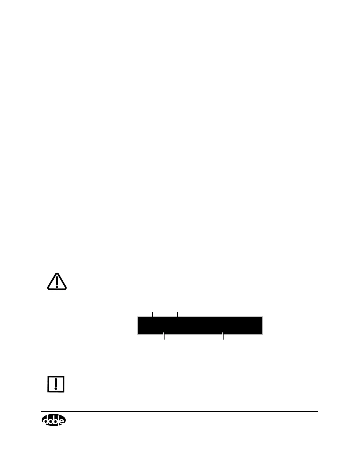
A series of messages appear in the display on the instrument front panel as the F6300
firmware boots up. These messages track the sequence of steps in a successful bootup. At the
end of this series of messages, the information in
Figure 3.1 appears in the display.
F6300 Version 4.10
CPU2 ID: 9939318 IP:10.1.3.1
Instrument
Model #
Firmware
Revision #
Identification # of the
CPU in the instrument
Instrument
IP Address
Figure 3.1 Display Information
NOTE If an error message appears in the VFD at the end of the bootup sequence, refer to Chapter 4
”Troubleshooting the F6300”.
The F6300 Instrument is controlled via the F6300 Control Panel Version 2 installed with
ProTesT 2.02 software. ProTesT 2.02 or later requires the following hardware and software: