CPU1 and CPU2 Circuit Boards
4-6 72A-2337-01 Rev. B 11/05
CPU1 and CPU2 Circuit Boards
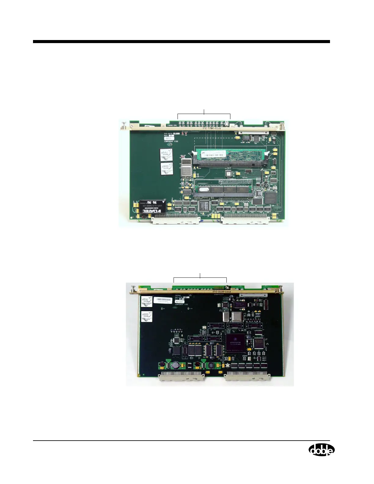
Either the CPU1 (Figure 4.4) or the CPU2 (Figure 4.5) circuit boards are installed in slot 3. Both
boards have twelve LEDs located at the top and one push button.
LEDs and RESET Button
Figure 4.4 CPU1 Circuit Board
LEDs and RESET Button
Figure 4.5 CPU2 Circuit Board
The LEDs indicate communication status (either RS-232 or Ethernet) and are described in
Table 4.2. The RESET push button activates a new power diagnostic cycle when pressed.