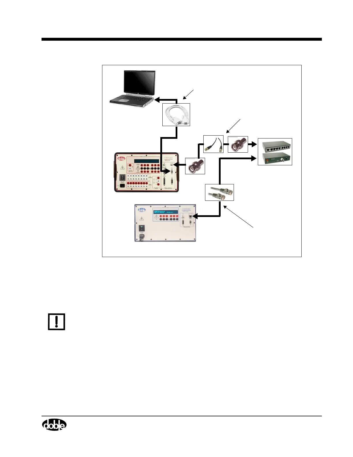
CPU1 F6150
CPU2 F6300
DB9 - DB9 Modem Serial (401-0167)
Cable to/from the PC Serial Port or USB-
Serial Adapter and the CPU1 F6150
PC RS 232 connector.
(401-0244)
10BaseT/10Base2 HUB
BNC-BNC RG58 50Ω Coaxial cable
(181-0118) with 50Ω terminators
(401-0157) on both ends of the cable
to/from the HUB and the CPU1 6150
NETWORK connector.
CAT5 or better Ethernet cables
(
401-0243
) to/from the NETWORK
connector on the CPU2 F6300
and the HUB.
F6300 Power System Simulator User Guide
72A-2337-01 Rev. B 11/05 2-13
Figure 2.16 Computer to CPU1 F6150/CPU2 F6300
Low Level Source Connections
The F6150 and F6300 each come equipped with a low level source connector.
NOTE The male/male DB15 cable supplied with the F6300 MUST BE connected between the LOW
LEVEL SOURCES connectors of both instruments. This cable connection is required for the
proper operation of the F6300.
To connect the F6150 and F6300 for Ethernet serial communication for:
• Three voltages and nine currents
• Three voltages and three currents
1. Connect a RG-58 coax cable with 50 Ohm terminators at each end or CAT5 or better
crossover cable at the NETWORK 10Base2 Ethernet connector of each instrument
(
Figure 2.17).
2. Connect a DB15 cable with male connectors on each end at the LOW LEVEL SOURCES
connector of each instrument.